SNLU262A december 2019 – june 2023 DP83826I
2.2.2 Power Inputs
 Figure 2-4 DP83826EVM Power Inputs
In the case the user would like to power the EVM from external sources, J7, J8, and J9, VDDA, VDDIO and the fiber optic transceivers respectively, can be removed and supplied power at pin 2 for all three jumpers. J23 (5V jumper) is used to supply LDO and PHY using an external 5V power supply. MSP is powered through USB.
DP83826EVM USB Power Input
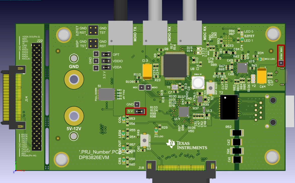
Remove the J23 jumper (5V jumper) and connect the right hand side pin to USB_VBUS using two female connector. After connection, PHY and MSP can be power up through USB without any external power supply required.