SNLU284 May 2020 LMH9135
3.3 Noise Figure Test Setup
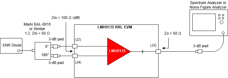
 Figure 3-3 Noise Figure Test Setup
Use the following guidelines for Noise Figure (NF) measurement:
- The traditional Y-factor method can be used for the NF measurement using a noise diode and a spectrum analyzer (or a noise figure analyzer), as Figure 3-3 shows.
- While doing the measurement, take into account any RF cable losses to the EVM board and also the balun loss. Any external input attenuator added for matching will result in proportional NF degradation and must be calibrated out in the measurement.
- Also, onboard losses of the input traces at the device input pin must be factored into the NF measurement.
- If the device output loss is significant, it is important to factor the output loss into the NF measurement.
- Use the Friis equation to calculate the combined NF of the measurement setup and then back calculate the individual device noise figure.