SNLU289 September 2020 DP83TG720R-Q1 , DP83TG720S-Q1
1.1 Overview
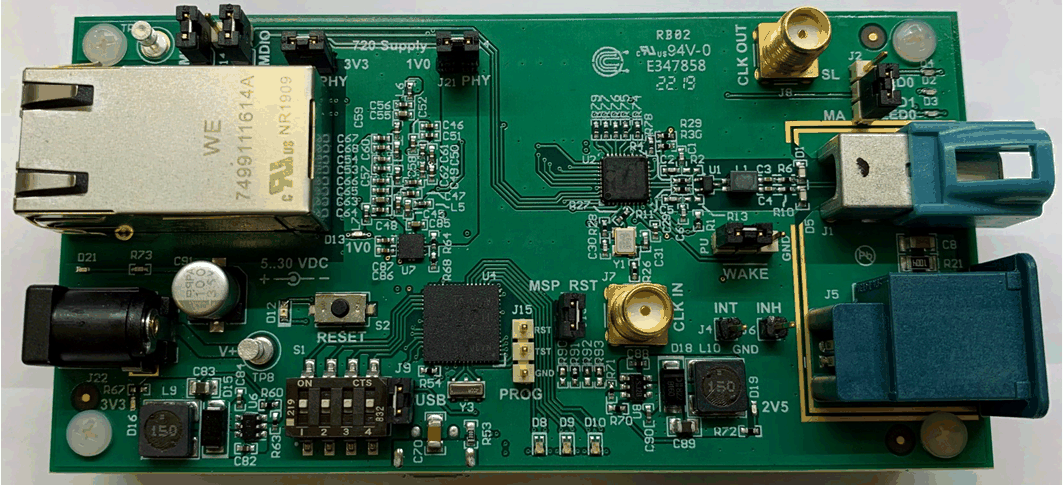
 Figure 1-1 Ethernet Media Converter Board
This Media Converter is a tool to connect automotive gigabit Ethernet network to a 1000BASE-T1 twisted pair network using the DP83TG720-Q1 automotive Ethernet PHY. It is an easy way to evaluate the functionality of the DP83TG720-Q1 PHY within a standard computer network environment.
The Media Converter is supported by USB-2-MDIO Tool, a command line Interface and DIEP, a user interface for reading and writing all control and status registers of PHYs over a USB connection for simple debugging and startup, on this board from the DP83TG720 and the DP83867 PHY.
For easy testing and development, this converter also comes with a pre-programmed MSP430, with different modes which can be selected via four DIP-Switches. It is possible to select from a standard configuration of the PHYs
For simple debugging, the converter provides onboard LEDs to show link qualityand which mode is selected. Further at the RJ45 Jack are LEDs to show speed selection and data transfer.
When more detailed information is required, the converter can send status and error information via USB to a simple terminal program.