SNVAA39 April 2022 LM5013 , LM5013-Q1
2 LM5013 PCB Comparison and Thermal Capability
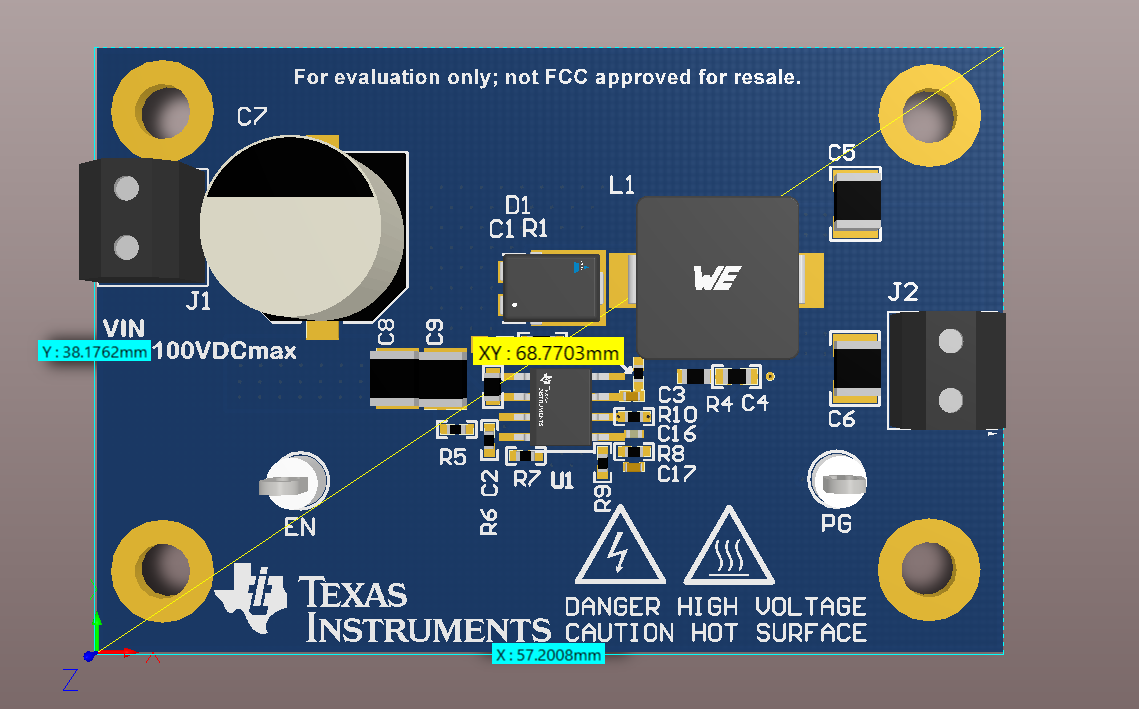
The LM5013-Q1EVM was designed to showcase the small solution size shown in Figure 2-1 that Texas Instruments can offer for a high-voltage regulator. A consequence of the small Figure 2-2, is reduced thermal performance. The LM5013-Q1 100-V Input, Automotive 3.5-A Non-Synchronous Buck DC/DC Converter with Ultra-low IQ includes plots (Figure 2-3) that demonstrate how increased PCB copper area results in reduced RΘJA. The equations used to perform the thermal analysis are also shown in the data sheet.
 Figure 2-1 LM5013-Q1EVM Schematic
 Figure 2-2 LM5013-Q1EVM 3-D image
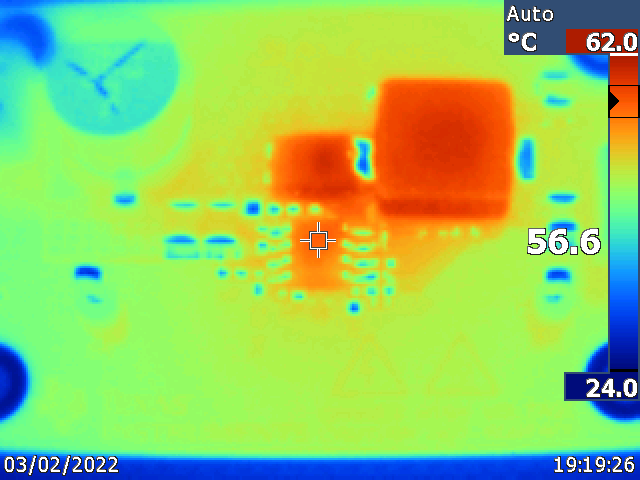
Figure 2-4 shows the corresponding thermal rise on the LM5013-Q1EVM with a 48-V input and a 1.75-A load. The IC power loss is determined to be 1.02W, corresponding to an approximate 32.83°C/W RΘJA for the 21.6cm2 , 4-layer board. This calculation was based on the estimated junction temperature (top case temperature) of the IC from the thermal capture taken.
 Figure 2-4 Thermal Rise on LM5013-Q1EVM (21.6cm2 , 4-layer board)
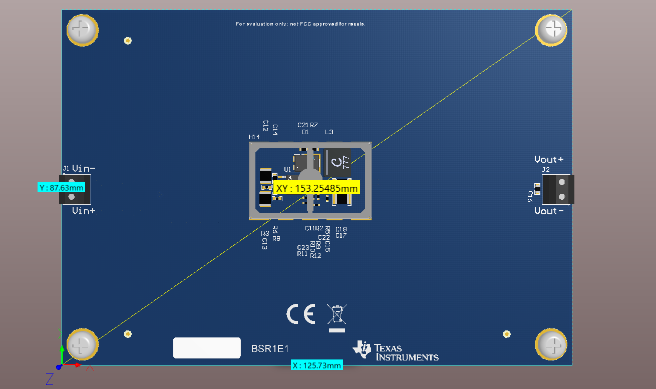
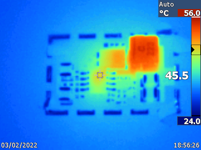
Figure 2-4 shows the corresponding thermal rise on an experimental LM5013-Q1 PCB design with a 48-V input and a 1.75-A load. The layer stackup of the PCB is identical to LM5013-Q1EVM, though, the corresponding board size changes from 5.7 cm by 3.8 cm to 8.7 cm by 12.7 cm. In addition, the inductor physical cubic area remained similar, though, the typical DCR was reduced from 64 mΩ (Wurth 74437368220) to 55 mΩ (Coilcraft XAL6060-223ME). The IC power loss of 1.05 W equates to an approximate 21.40°C/W RΘJA for the 110cm2 , 4-layer board.
 Figure 2-5 Experimental LM5013 PCB 3-D image
 Figure 2-6 Thermal Rise on Experimental LM5013 PCB (110cm2 , 4-Layer Board)
As shown, the increase in copper area of the experimental PCB reduces the case temperature, and therefore the approximate junction temperature, by 11°C. Additional considerations need to be taken into account when considering thermal optimization or analysis, namely the power inductor used in the design, as well, the buck diode.