SNVAA39 April 2022 LM5013 , LM5013-Q1
3 Buck Inductor and Asynchronous Diode Impact on Thermals
Data sheets of DC/DC regulators recommend the buck diode and inductor to be in close proximity to the regulator. Closely placed components aids in reduction of EMC by the fact the high amplitude and high frequency AC current, whose loop is formed by these external components, are minimized, as well, their copper area which is proportional to radiated noise, is reduced. With these components conducting substantial DC current, in the case of a low duty cycle application for the asynchronous diode and high load current applications for the inductor, their power dissipation and corresponding temperature rise can influence the temperature rise in the neighboring regulator.
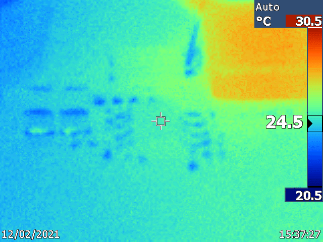
One main, targeted application for this device is 48-V to 12-V conversion. In a buck topology, the corresponding AC losses (of the inductor and diode) are not as of high importance in comparison to DC losses considering they are often small with correct component selection. The corresponding conduction loss (DC) in the inductor would be: LDCR *Iout2 , with LDCR being the diode series resistance and Iout being the load current. Figure 3-1 shows the corresponding temperature rise on the LM5013-Q1EVM’s for the buck inductor passing 1.75-A, a 1.75-A continuous load. As illustrated, that the PCB which was evaluated at ~23°C ambient exhibits about ~7°C rise in the buck inductor which constitutes ~1.5°C rise in the regulator.
 Figure 3-1 Inductor Self-Heating Impact
on Neighboring Regulator
Figure 3-1 Inductor Self-Heating Impact
on Neighboring RegulatorThe other power component in close proximity to the regulator is the asynchronous diode. The corresponding conduction loss associated with it is: VD *(1-D)*Iout , VD being the forward voltage drop of the diode and D the duty cycle.
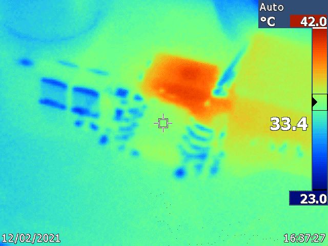
The average diode current ((1-D)*Iout ) is 1.3-A for a 48-V to 12-V conversion with a 1.75-A continuous load. Figure 3-2 demonstrates that the PCB evaluated at ~23°C ambient with the inductor biased with 1.3-A. It shows about ~17°C rise in the buck diode which constitutes ~10°C rise in the regulator.
The diode (Vishay V8P12-M3/86A) was biased with 1.3-A, resulting in ~17°C rise in it and 10°C rise in the disabled regulator
 Figure 3-2 Diode Self-Heating Impact on
Neighboring Regulator