SPRAD55 March 2023 TMS320F2800132 , TMS320F2800133 , TMS320F2800135 , TMS320F2800137 , TMS320F2800152-Q1 , TMS320F2800153-Q1 , TMS320F2800154-Q1 , TMS320F2800155 , TMS320F2800155-Q1 , TMS320F2800156-Q1 , TMS320F2800157 , TMS320F2800157-Q1 , TMS320F280021 , TMS320F280021-Q1 , TMS320F280023 , TMS320F280023-Q1 , TMS320F280023C , TMS320F280025 , TMS320F280025-Q1 , TMS320F280025C , TMS320F280025C-Q1 , TMS320F280033 , TMS320F280034 , TMS320F280034-Q1 , TMS320F280036-Q1 , TMS320F280036C-Q1 , TMS320F280037 , TMS320F280037-Q1 , TMS320F280037C , TMS320F280037C-Q1 , TMS320F280038-Q1 , TMS320F280038C-Q1 , TMS320F280039 , TMS320F280039-Q1 , TMS320F280039C , TMS320F280039C-Q1
4 Software
The example used for this application note utilizes SysConfig with driverlib for the configuration of the ADC, ePWM, and other peripherals. Within the program code, the ADC should be set up to minimize overhead such that more time can be used between conversions to do a control loop. For the example used in this application note, the SOCs are configured in burst mode with round-robin priority, so that the SOCs are triggered together and accumulated without missing a value when oversampling. An interrupt is set up to trigger once the last SOC, SOC15 for F28003x, reaches the end of conversion. The interrupt runs the corresponding ISR, which stores the ADC result and accumulate multiple SOC results if oversampling is enabled.
The ePWM triggers the SOCs here, however software triggers and CPU timer triggers are also available. Take care when choosing the period of the trigger to maintain uniform sampling of the SOCs, and appropriate conversion time with respect to the rest of the control loop. Once the last SOC in the burst sequence issues an end-of-conversion signal, the ISR executes the control loop. In this example, the control loop consists of a simple accumulation function for oversampling and storing the results. Avoid averaging the values because this effectively reduces measurement precision by discarding information contained in the lower bits of the result. The final result is stored in memory before the next burst is triggered.
Below is an example of baseline sampling with the burst ISR setup:
__interrupt void adcA1ISR(void)
{
    //
    // Clear the interrupt flag
    //
    ADC_clearInterruptStatus(ADCA_BASE, ADC_INT_NUMBER1);

    //
    // 1X Oversampling
    //
    lv_results[nloops++] = ADC_readResult(myADC0_RESULT_BASE, ADC_SOC_NUMBER0);

    //
    // Check if overflow has occurred
    //
    if(true == ADC_getInterruptOverflowStatus(ADCA_BASE, ADC_INT_NUMBER1))
    {
        ADC_clearInterruptOverflowStatus(ADCA_BASE, ADC_INT_NUMBER1);
        ADC_clearInterruptStatus(ADCA_BASE, ADC_INT_NUMBER1);
    }

    //
    // Check if all results are stored
    //
    if(nloops >= numBins)
    {
        //
        // Disable ADC interrupt
        //
        ADC_disableInterrupt(myADC0_BASE, ADC_INT_NUMBER1);
        ESTOP0;
    }

    //
    // Acknowledge the interrupt
    //
    Interrupt_clearACKGroup(INTERRUPT_ACK_GROUP1);
}
An example of oversampling a signal at 8X with ISRs is as follows:
__interrupt void adcA1ISR(void)
{
    //
    // Clear the interrupt flag
    //
    ADC_clearInterruptStatus(ADCA_BASE, ADC_INT_NUMBER1);

    //
    // Accumulate 8 ADC results to oversample 8X
    //
    lv_results[nloops++] = (ADC_readResult(myADC0_RESULT_BASE, ADC_SOC_NUMBER0) + ADC_readResult(myADC0_RESULT_BASE, ADC_SOC_NUMBER1) +
            ADC_readResult(myADC0_RESULT_BASE, ADC_SOC_NUMBER2) + ADC_readResult(myADC0_RESULT_BASE, ADC_SOC_NUMBER3) +
            ADC_readResult(myADC0_RESULT_BASE, ADC_SOC_NUMBER4) + ADC_readResult(myADC0_RESULT_BASE, ADC_SOC_NUMBER5) +
            ADC_readResult(myADC0_RESULT_BASE, ADC_SOC_NUMBER6) + ADC_readResult(myADC0_RESULT_BASE, ADC_SOC_NUMBER7));

    //
    // Check if overflow has occurred
    //
    if(true == ADC_getInterruptOverflowStatus(ADCA_BASE, ADC_INT_NUMBER1))
    {
        ADC_clearInterruptOverflowStatus(ADCA_BASE, ADC_INT_NUMBER1);
        ADC_clearInterruptStatus(ADCA_BASE, ADC_INT_NUMBER1);
    }

    //
    // Acknowledge the interrupt
    //
    Interrupt_clearACKGroup(INTERRUPT_ACK_GROUP1);
}
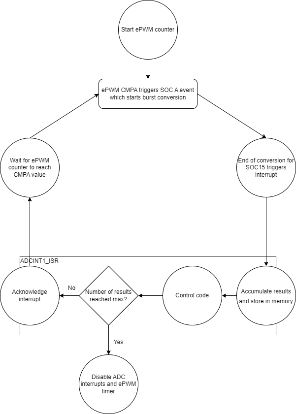
The appropriate interrupts can be disabled once the intended number of results have been stored, or else the ADC can continue to convert the analog signal. The basic flow of using an ePWM to trigger the burst conversion for oversampling is shown in Figure 4-1.
 Figure 4-1 SoC Flow Diagram for
Oversampling
Figure 4-1 SoC Flow Diagram for
OversamplingDepending on the control loop for the specific application, more time may be required than what the max sampling rate of the ADC allows. To solve this, increase the ePWM time base to allow a longer conversion time, giving the control loop more time to complete. This reduces the maximum frequency that can be properly measured, since the ADC does not trigger as often.
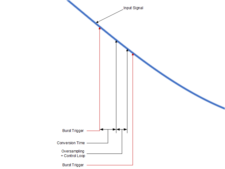
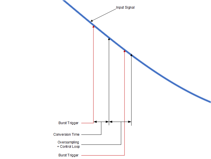
The input frequency affects the oversampling factor that can be used. For signals that are at a higher frequency or need to be sampled at a higher rate, a lower oversampling factor is necessary because of the software overhead required. To determine the maximum input frequency where data is not likely to be missed, the number of cycles needed for the control loop and oversampling are needed. The control loop cycle count includes any user-related operations such as ISR handling or processing that need to happen every time new samples are obtained. Figure 4-2 shows where these timings come into play when sampling a signal. In this image, the oversampling and control loop time includes system clock cycles for interrupt latency and ISR execution. Notice that there is some buffer time between the end of the control loop and the arrival of the next ADC trigger, so that processing does not prevent a trigger from occurring and data is not missed. Figure 4-3 shows that when the total time for conversions, oversampling, and the control loop exceeds the burst trigger period, data is missed. The solution for this is to extend the period, which in this example would require extending the ePWM time base to move the trigger further.
Table 4-1 shows the timings of the oversampling used in this application note, which includes time for reading results from the ADC register, accumulating values if necessary, and storing the result in RAM. The timings for this table were taken with only the --opt_for_speed = 5 for optimization, so the timings are not necessarily the minimum achievable values. For more details on how to improve the speed of a program, see the C2000 C28x Optimization Guide.
If the control loop timing is not known, a simple GPIO toggle is accurate enough to determine the period of this loop. The function below can be used to route the SOC A event trigger to the corresponding external pin. This can be used to verify the event is triggering properly, and that the ISR has sufficient time to run before the burst gets triggered again.
SysCtl_enableExtADCSOCSource(SYSCTL_ADCSOC_SRC_PWM1SOCA) Figure 4-2 Timings for Sampling a
Signal
 Figure 4-3 Incorrect Timings for Sampling
a Signal
Figure 4-3 Incorrect Timings for Sampling
a Signal| Oversampling Factor | Oversample Time (clock cycles) |
|---|---|
| 1X | 9 |
| 2X | 52 |
| 4X | 127 |
| 8X | 272 |
| 16X | 551 |
Take for example a control loop within an interrupt service routine (ISR) that takes about 300 cycles to run. Measuring a sine wave at 16X oversampling with ISR uses 851 cycles. If the sine wave is 10 kHz, based on the Nyquist theorem, the minimum sampling rate is at least 20 kSPS (kilo-samples per second). The table in the ADC Timing Diagrams chapter of the TMS320F28003x Real-Time Microcontrollers Technical Reference Manual shows how tLAT increases with larger ADC clock prescale values. SYSCLK is the system clock frequency. This is 120 MHz by default for the TMDSCNCD280039C. For an ADC clock of 60 MHz on the TMDSCNCD280039C, the clock prescaler divides SYSCLK by 2, and the value for tLAT is 23 SYSCLK cycles. FSample is the rate in samples per second required for a specific application, which is 20 kSPS here.
In this example the maximum acquisition window size (ACQPS), based on the above formula, is 5,976. This value is very large only because the sampling rate does not have a very high requirement. Having a maximum ACQPS value is important so that there is sufficient time to sample an input without missing significant data points, as the ACQPS itself is determined by the input network. For more information on calculating ACQPS values, see the Choosing an Acquisition Window Duration section within the ADC chapter in TMS320F28003x Real-Time Microcontrollers Technical Reference Manual. The maximum input frequency measurable with this example setup is about 67 kHz, given the Nyquist rate. For comparison, the data collected in this application note was sampled at about 3 MSPS, which can only be achieved by using an ACQPS value of 16 or less. The maximum input frequency measurable using this sample rate was about 74 kHz, given that the ISR time was about 211 cycles.