SSZT212 December 2020 DAC53401 , DAC53701
Sanjay Pithadia co-authored this article.
In our previous post, we talked about medical alarms and their compliance requirements. Now, let’s talk about the design inputs and existing implementation methods for medical alarm systems.
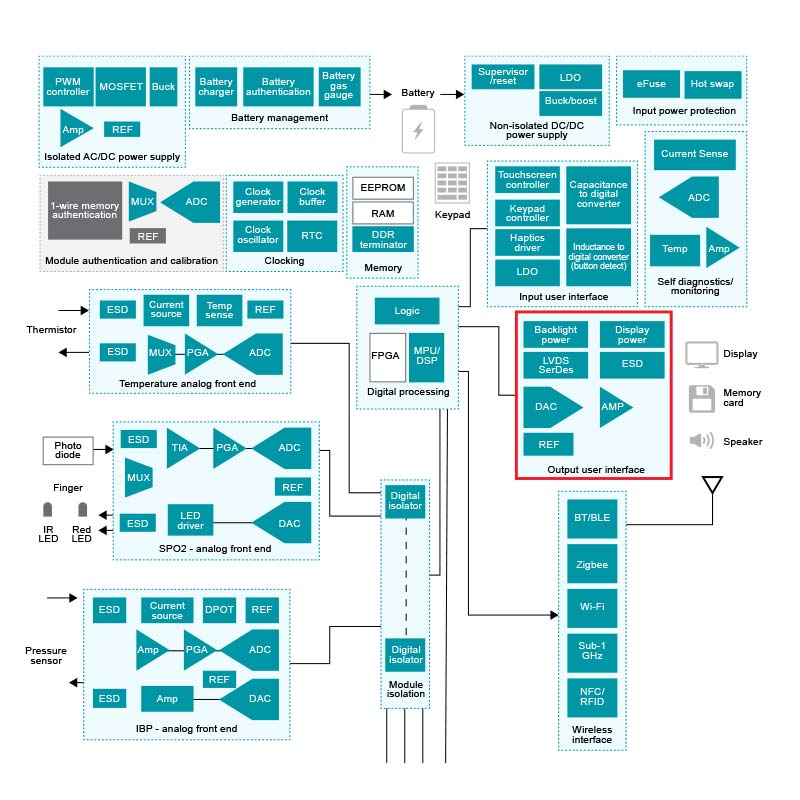
Figure 1 shows a high-level block diagram of multiparameter patient monitor. The block outlined in red represents the output user interface which can drive the display and speakers for the visual and audio alarms, respectively. This subsystem is common in most medical equipment. Based on the specific requirements of the end-equipment and expected failure conditions, designers use different techniques for generation the alarm tones. We will discuss the most common design inputs and implementation schemes in this article.
 Figure 1 High-level Block Diagram of
Multiparameter Patient Monitor
Figure 1 High-level Block Diagram of
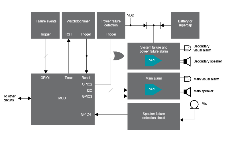
Multiparameter Patient MonitorFigure 2 shows a block diagram of a medical device alarm implementation. One of the main requirements of a medical device design is that it needs to be single-fault proof. A “single-fault condition” in medical equipment refers to the presence of a single independent abnormal condition. During a single-fault condition, a medical device must provide basic safety from physical hazards and minimum functionality, known as “essential performance.” An alarm is part of the essential performance for most therapeutic and all critical-care medical devices. Hence, the alarm function needs to be single-fault proof.
The list of single-fault conditions for a medical alarm includes:
- A failure of the primary driving source for the alarm such as a microcontroller (MCU).
- A failure of the mains power for mains-operated equipment.
- A discharge or failure of the battery for battery-powered equipment or equipment with a battery backup.
- A failure of the main alarm circuit – auditory or visual.
For medical devices where the time to respond to a failure is not very critical, the auditory and visual alarms can complement each other as redundant alarm functions. In critical-care equipment such as a ventilator, however, the response time to a failure is critical.
 Figure 2 Possible Implementation of an
Alarm System in Medical Equipment
Figure 2 Possible Implementation of an
Alarm System in Medical EquipmentAs you can see in Figure 2, the alarm subsystem implements redundancy by using two sets of visual and auditory alarms. The failure of the main alarm function is detected using a coincidence circuit, which typically includes a microphone placed close to the speaker to monitor the sound level. A sound received by the microphone that is not the same as the sound generated by the circuit will register an error condition. TI’s alarm tone generator reference design implements an example coincidence circuit.
There are multiple existing ways to implement the alarm functionality, such as with an MCU, a field-programmable gate array (FPGA) or complex programmable logic device (CPLD), an integrated buzzer, an audio codec, or with discrete operational amplifiers and glue logic. All of these techniques have pros and cons. Table 1 compares different implementation techniques in terms of configurability, usability, cost, bill of materials and applicability to the different end equipment.
| Hardware-only solution | Audio chip | Microcontroller | Integrated buzzer | FPGA/CPLD | |
|---|---|---|---|---|---|
| Components | Tone generator, envelope generator, volume control, audio amplifier, speaker | Audio chip, audio amplifier, speaker | Microcontroller, amplifiers, analog mixer, audio amplifier, speaker | Integrated buzzer | FPGA/CPLD, audio digital-to-analog converter/codec, audio amplifier, speaker |
| Pros |
|
|
|
|
|
| Cons |
|
|
|
|
|
One technique for implementing a medical alarm uses DAC53701, a 10-bit smart digital-to-analog converter (DAC) that supports medical alarm generation using pre-programmed waveforms. This DAC can be used for both auditory and visual alarm generation, and it supports configurability of the pulse frequency and the timings for the pulse envelope and the burst. You can read more about this technique in the application brief, Demystifying Medical Alarm Designs With Smart DACs.
Additional resources:
- Learn more about TI’s technologies for medical applications.