SSZT570 december 2018 TMP117
Other Parts Discussed in Post: TMP117
For the highest accuracy temperature measurement, system designers have traditionally had only one option: platinum resistive temperature detectors (RTDs) such as the PT100 or PT1000. Highly linear and interchangeable, RTDs are available in a wide range of accuracy classes as defined by International Electrotechnical Commission (IEC) and Deutsches Institut für Normung e.V. (DIN) standards down to ±0.03°C of error at 0°C. However, achieving this level of accuracy with RTDs doesn’t come easily.
To attain the highest accuracy available with RTDs, it often takes anywhere from hours to days to carefully select and simulate expensive precision components surrounding the RTD. A designer must also be extremely diligent with the board layout to avoid resistance mismatches which can easily skew measurements.
Despite a designer’s meticulous efforts, the acquisition circuitry can easily add 0.5°C to 1.0°C of measurement error, dwarfing the inherent accuracy of the RTD itself. To achieve accuracy that is close to what the RTD can offer, the only option is the time-consuming and expensive process of calibrating each unit in production.
| Save time in your design | |

|
Learn more by reading the application note, “RTD Replacement in High Accuracy Sensing and Compensation Systems Using Digital Temperature Sensors.” |
To tackle the design challenges in using RTDs, TI recently introduced the TMP117 family of digital temperature sensors which provides accuracy comparable to Class-AA RTDs while dramatically simplifying design efforts. As shown in Figure 1, the TMP117 offers accuracy of +/-0.1oC from -20oC to 50oC and 0.3oC accuracy across a full operating range of -55oC to 150oC with no calibration during manufacturing required.
 Figure 1 IEC 60751 RTD Accuracy Classes
vs. TMP117
Figure 1 IEC 60751 RTD Accuracy Classes
vs. TMP117Note: The RTD lines represent error of each accuracy class per IEC 60751 and does not include measurement error or calibration which will impact the final system-level accuracy.
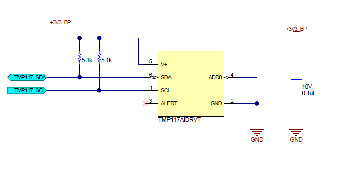
From a design stance, the contrast between designing with an RTD verses an IC temperature sensor couldn’t be starker (see Figure 2).
VS.
 Figure 2 Circuit Comparison for a
Typical RTD vs. TMP117
Figure 2 Circuit Comparison for a
Typical RTD vs. TMP117By combining the sensor and analog-to-digital converter (ADC) onto a single chip, a digital temperature sensor like the TMP117 dramatically simplifies many of the most time-consuming and difficult aspects of RTD designs and provides a direct temperature readout across an I2C interface. Table 1 shows a detailed comparison on the design efforts needed between the two technologies.
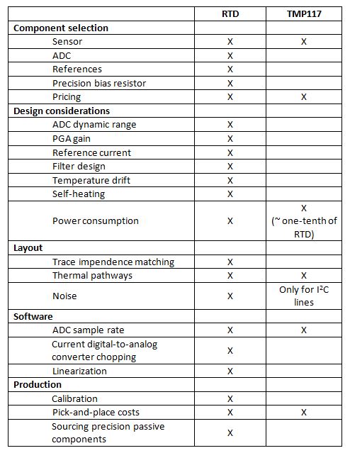
|
For an alternative to platinum RTDs for applications that need the highest accuracy, check out the TMP117. Its integration provides unprecedented simplicity, while also simplifying and reducing costs at production.
Additional Resources
- Read more about this topic in the application note, “RTD Replacement in High Accuracy Sensing and Compensation Systems Using Digital Temperature Sensors.”
-
See how the differential temperature measurement (DTM) subsystem of heat and cooling meters provides a fully digital alternative to thin-film platinum RTD sensors using the “Replacing platinum RTD sensors with digital temperature sensors” reference design.
- Check out all of TI’s temperature sensor integrated circuits (ICs).