SSZT739 April 2018 TPS82130 , TPSM84209 , TPSM846C24
Power modules are becoming increasingly popular in many market segments – the ability to buy a power supply that already includes the switching inductor is a big advantage. The main reasons engineers are choosing power modules as opposed to a discrete alternative are:
- Reduced Solution Size. Power Modules are typically smaller than what designers can easily develop on their own. The ability to integrate active circuitry under the inductor can significantly reduce solution size and enables you to put more functions in a smaller space
- Reduced Development Time. Power Module designers are power experts; they put tremendous effort into ensuring the components used in the module are reliable and of the right value to ensure excellent performance. They choose the optimal control topology and confirm the layout is of high quality. The result is a solution that is robust, high performance and easy to use.
In order for the power module market to continue to expand, the modules need to continue to get smaller and include more compelling features.
Power modules are built with several different manufacturing techniques, each with pros and cons. Figure 1 highlights some of the different approaches, including embedding the integrated circuit (IC) in a laminate, putting components onto a laminate and overmolding (or not), or putting components onto a metal leadframe and overmolding.
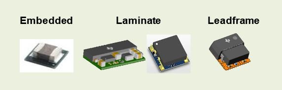
Example of Various Package Types Offered by Texas Instruments
Another factor to consider when developing a power module is how the IC is packaged. An unpackaged IC is best, as it is smaller and costs less than a packaged alternative. But it is more difficult to handle and test in production, and until now has not been a common approach. Most power modules either embed the silicon in the laminate and place the inductor over the top, or use a packaged IC mounted onto a leadframe or laminate.
In order to address the need for small size and good thermals, TI has added a new package approach to its portfolio. Called flip chip on leadframe (FCOL), a bumped die is mounted onto a leadframe along with passive components and then overmolded. TI has just released its first product with this new technology, the TPSM84209. (See Figure 2 for a look at how the module looks from the inside and outside.)
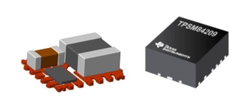
A More Detailed Look at the inside and outside of the TPSM84209 Power Module
Smaller Package Size.
Overmolded Package.
Improved Thermals.
Good Emi.
Excellent Reliability.
 Figure 1 TPSM84209 Efficiency vs Output Current
 Figure 2 Safe Operating Area 12Vin, 5Vout
There is no single package technology that is suitable for every product or application requirement. TI uses several different technologies to enable the optimal module performance at different power levels. The new FCOL package is a good new option for when size is a key concern. Get more information on TI’s DC/DC power module portfolio.