SSZT748 april 2018 TPS2051C , TPS25810 , TPS25820 , TPS25821 , TUSB544
USB Type-C™ adoption into the personal electronic space is ramping up. Many system and product definers are asking if they should convert USB Type-A ports into USB Type-C ports, and what that entails.
There are benefits and costs to making the switch. Besides the obvious advantage of having the new USB Type-C connector, which is easier for customers to use and has a smaller form factor, the system also becomes more energy-efficient. TI has a family of products that make the conversion very straightforward.
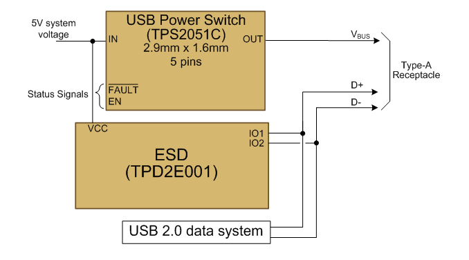
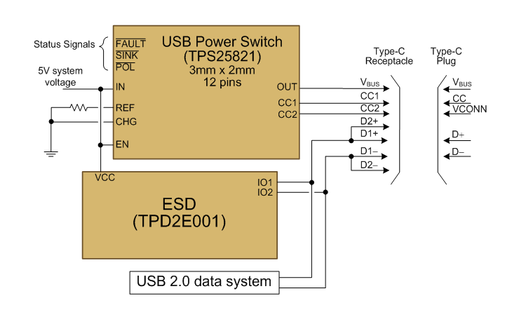
In this post, I want to focus on USB 2.0 and USB 3.1 data systems that are 5V only. The conversion is simplest for a USB 2.0 system. Figure 1 shows a typical schematic for a USB 2.0 Type-A system. Converting this system to USB Type-C is just a matter of replacing the USB power switch, as shown in Figure 2. TI has a large portfolio of USB Power Switches for Type-A ports, so this blog is to help those using power switches such as the TPS20xxC family know how to convert to Type-C ports.
 Figure 1 Traditional USB 2.0 Type-A
System Using a TPS2051C USB Power Switch
 Figure 2 USB 2.0 Type-C System
The first thing to notice about the USB Type-C power switch is that it has more pins and more features. The configuration channel (CC) pins CC1 and CC2 perform the USB Type-C functionality. USB Type-C allows the source to change its advertisement dynamically, so TI’s TPS25821 advertises either 0.5A or 1.5A, for example, based on the state of the CHG pin.
USB Type-C hosts are required to disable VBUS when nothing is attached. This cold-socket requirement has the great advantage of allowing systems to reduce quiescent current. For example, the TPS2051C in Figure 1 must remain enabled even when there is no cable attached – and will be consuming 80µA. In contrast, the TPS25821 will not apply voltage to the OUT pin when the receptacle is empty and will consume only 1µA. The TPS25821 also indicates whether the receptacle is empty via the pin, which the system may use to reduce quiescent current.
A USB Type-C receptacle has two pairs of USB 2.0 data contacts, but they are shorted together because the Type-C cable only has one pair of USB 2.0 data wires.
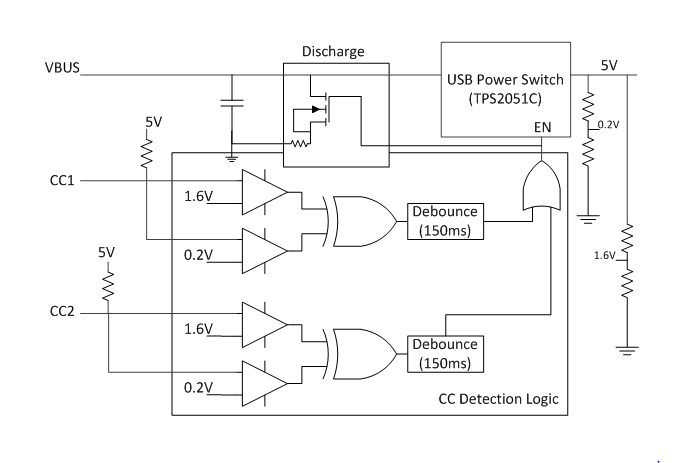
Before moving on to USB 3.1 systems, it may be a good idea for me to pause here and explain why it is not a good idea to try to implement a discrete solution. It is important that VBUS be low when the USB Type-C receptacle is empty. A USB Type-C system can connect to a USB Type-A port through an A-to-C cable. Since the USB Type-A port VBUS will always be about 5V, if the connection happens when the USB Type-C port is not cold-socket, the port with the higher VBUS voltage will drive current into the other port. Many USB Type-A port power switches do not have reverse-current protection, so they could be damaged if driven to a higher voltage.
Figure 3 shows a discrete USB Type-C implementation that implements the cold-socket requirement. It is much simpler to just use a USB Type-C power switch!
 Figure 3 Discrete USB 2.0 Type-C
System
Figure 3 Discrete USB 2.0 Type-C
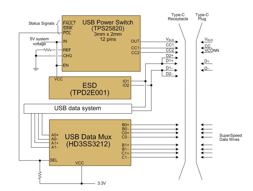
SystemIn Figure 2, the pin on the USB power switch is unused because it is a USB 2.0 system. When converting to a USB 3.1 system, however, the pin becomes very important because the flip-ability of the USB Type-C plug requires a SuperSpeed multiplexer. You cannot use the USB 2.0 stubbing trick for USB 3.1 systems because there are eight SuperSpeed data wires in a USB Type-C cable, not just the four being used. Stubbing signals together would cause the signal to travel back through the cable again, and at the short wavelengths of USB 3.1 signals, the reflections would totally kill the signal.
There is another major change in the USB Type-C ecosystem that affects the requirements for a USB Type-A to USB Type-C conversion. Since a USB 3.1 Type-C cable may be connected in systems where VBUS reaches 20V, the VBUS wire can no longer directly power the active components in the cable (eg. a signal redriver such as TUSB544). Therefore, the electronics in the plug need a low-voltage supply from the USB Type-C host. USB Type-C hosts are required to provide this low-voltage supply onto the plug’s VCONN pin, which will be attached to either the CC1 or CC2 pin in the receptacle depending on plug orientation. The TPS25821 used in Figure 2 for USB 2.0 does not have VCONN capability, but the TPS25820 used in Figure 4 will automatically apply voltage to and discharge the VCONN pin of the cable according to USB Type-C specification requirements.
Figure 4 shows the simplest implementation for converting a USB 3.1 Type-A system (not showing the electrostatic discharge [ESD] of the SuperSpeed lines for simplicity). The TPS25820 pin controls the multiplexer so that the correct signals get routed to the USB 3.0 data system, but the addition of a multiplexer is a new burden for USB 3.1 systems.
 Figure 4 USB 3.1 Type-C System
Finally, this post mainly targets USB systems that only provide the USB standard current. However, USB Type-C provides a simple way to increase the amount of current advertised without overloading the D+/D- wires as in the CDP mode of Battery Charging (BC) 1.2. For example, you can configure the TPS25820 and TPS25821 to offer either the USB standard current or 1.5A by pulling the CHG pin high or low, while the TPS25810 can offer up to 3A.
In summary, converting from USB Type-A to USB Type-C not only allows you to keep up with the latest technology trend, but it also provides for becoming more energy efficient and easily sourcing higher power.
Additional Resources
- Read the blog post, “Upgrading USB chargers from Type-A to Type-C”
- Read the blog post, “Power Tips: Power sharing in USB Type-C applications.”
- Check out these reference designs, “USB Type-A Plug to USB Type-C Receptacle SuperSpeed MUX with DFP Controller Reference Design” and "Barrel Jack to USB C PD and USB Type-A to USB Type-C TIkit Reference Design"