SSZT879 November 2017 LMZ20502 , LMZ21700 , LMZ31530 , LMZ31704 , LMZ31710
Over the last three installments of this series, I have gone over some basic design considerations for creating a power supply for field-programmable gate arrays (FPGAs). Now that you have determined the power requirements and identified some necessary feature and performance specifications, you are ready to pick parts!
One way to simplify FPGA power if you are a new designer (or strapped for time) is to choose modules as your power supplies. Modules integrate the inductor as well as other passive components to create an easy solution with minimal design. Many of our modules require only three components: the input capacitor, output capacitor and a resistor to set the output voltage. This helps create a small, compact footprint without needing expertise in power-supply layout.
Fewer components not only simplify the solution and reduce the amount of hours needed to design and debug, but also increase reliability. Using a minimal number of components reduces the risk of faulty components or a mistake in the design. TI guarantees many performance parameters in its data sheets, including electromagnetic interference (EMI) performance, thermal performance and efficiency. This means that you can focus less on designing the power and more on adding value to the end product or getting to market quicker.
The disadvantage of a module is that there is less flexibility to optimize the solution through inductor or passive component selection. Modules are typically designed to work with common system architectures, so they are a good option unless you have a particularly stringent performance requirement. Modules can provide good performance and compact solution sizes for most power designs and can be an excellent option, especially for space-constrained, time-constrained or beginner power designers.
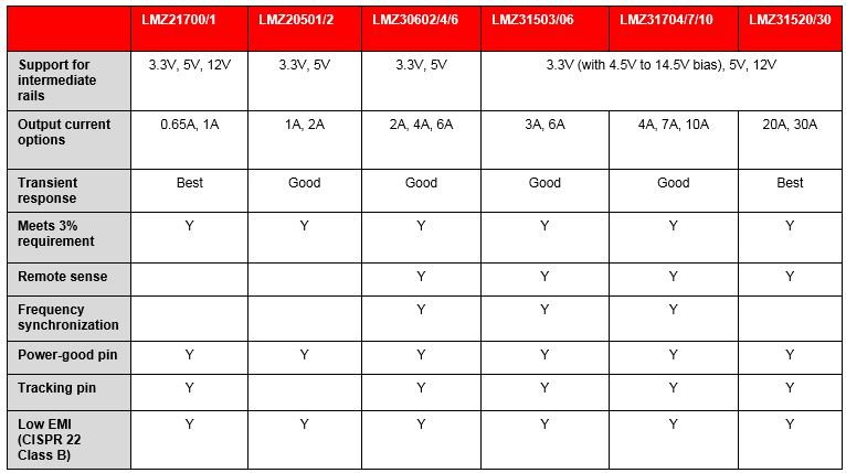
Table 1 lists a subset of devices from TI’s power module portfolio that meet the requirements for FPGA rails.
|
For rails that require large amounts of currents like the core rail, I recommend the LMZ31530/20 or LMZ31710/07/04, which are rated for 30A/20A or 10A/7A/4A, respectively, and meet the 3% tolerance requirement. These devices also have extra features – remote sense to improve load regulation and frequency synchronization, which can help reduce noise and power good for easy sequencing.
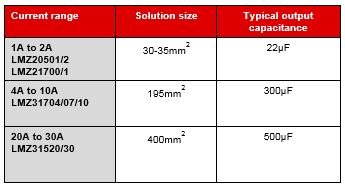
For the auxiliary and input/output (I/O), I recommend using TI’s LMZ21700/1 or LMZ20502/1 Nano Modules for the auxiliary rails or general-purpose I/O (GPIO) rails, or the LMZ31704/7/10 if you need higher current. An additional advantage to using Nano Modules is the size advantage. As Table 2 illustrates, Nano Modules in particular provide a very tiny solution size through a small 3mm-by-3mm package and require minimal external components, enabling you to easily save space.
|
The transceiver rails are often the most tricky to design for because of the tight noise requirements. Fortunately, all TI modules use shielded inductors and are tested to the Comité International Spécial des Perturbations Radioélectriques (CISPR) 22 Class B standard, which guarantees that the modules meet low-noise requirements. Some TI modules have a frequency synchronization feature to further reduce noise for applications like medical equipment, which is extremely noise-sensitive.
TI provides resources such as reference designs, which provide a ready-made solution that customers can use as a starting point. There is also a tool on WEBENCH® called FPGA Power Architect that can recommend parts and create a full design for you based off of your FPGA and power requirements.
To summarize, when starting a design I recommend starting with these basic steps:
- Use vendor tools to determine your current requirements.
- Check TI reference designs for a ready-made solution.
- Use WEBENCH FPGA Power Architect to create a design.
Following these steps will give you an excellent starting point; you can then continue to optimize the design to meet your exact requirements.
For more information on this topic, check out these resources on FPGA power designs:
- Watch the TI training video, “FPGA Power Made Simple.”
- Browse reference designs featuring Xilinx and Altera FPGAs.
- Read the Power Designer article, “Power Supply Design Considerations for Modern FPGAs.”