SSZT888 November   2017 LM5150-Q1


  1.   1
  2.   2
    1.     3
    2.     Small-signal Analysis
    3.     Large-signal Analysis
    4.     Error Amplifier to PWM Comparator Offset
    5.     Error Amplifier Sourcing Capability
    6.     Wake-up Delay
    7.     LM5150-Q1 Automotive Boost Controller
    8.     Conclusion
    9.     Additional Resources

Eric Lee

GUID-5D59D9B6-8A80-4B9C-BF8C-7CEC5099471A-low.jpg

The start-stop system in hybrid electric vehicles (HEVs) helps reduce fuel consumption and emissions by stopping the engine during idling, but the battery voltage drops whenever the engine restarts. To provide the minimum required voltage to the loads during the battery voltage drop, pre-boost converters are widely used in automobiles.

Table 1 shows the typical requirements for a pre-boost converter.

Table 1 Pre-boost Converter Specifications
Requirements
Input voltage Peak 40V, typical 12V, minimum 2.5V
Output voltage Maximum 40V, minimum 8.5V
Output current From 2A to 4A

In this blog post, I’ll explain the key parameters which affect the output-voltage undershoot of the pre-boost converter when the battery voltage drops.

Small-signal Analysis

According to the traditional small-signal analysis, there are two important parameters which affect the output undershoot: the loop response of the converter and the output impedance of the power stage. Table 2 shows the factors that optimize the loop response and output impedance.

Table 2 Factors That Improve the Loop Response and Lower the Output Impedance
Key parameters Factors for performance improvement
Fast loop response
  • High crossover frequency.
  • Fast switching.
  • Low-value inductor/high right-half-plane (RHP) zero frequency.
Low output impedance
  • High-value output capacitor.
  • High crossover frequency.

Large-signal Analysis

In addition to the two parameters in small-signal analysis, three more parameters in large-signal analysis affect the output undershoot: the error amplifier to pulse-width modulator (PWM) comparator offset, the error amplifier sourcing capability and the wake-up delay. Because all three parameters are device-dependent and none are user-adjustable or user-programmable, device selection is very important when designing a pre-boost converter.

Error Amplifier to PWM Comparator Offset

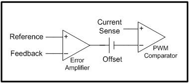
Traditional boost devices have about 1.2V offset from the error-amplifier output to the input of the PWM comparator (see Figure 1). Because the device cannot start switching until the error amplifier output is greater than the offset voltage, minimizing this offset is a key factor to improve undershoot during the battery voltage drop.

GUID-81D3DD81-C5E0-4284-BB49-0E18C1F141BF-low.jpg Figure 1 Controller Block of a Boost Device

Error Amplifier Sourcing Capability

Sometimes the undershoot increases due to the limitation of the error amplifier. Ideally, the gain of the error amplifier should be constant over the typical error amplifier operating range, but the gain drops if the error amplifier sourcing capability is insufficient.

Wake-up Delay

Because a pre-boost converter usually falls into a low quiescent current (IQ) standby mode to minimize battery drain when the battery voltage is in normal range, it takes some time to wake up the device from a low-IQ standby mode. Because the device cannot start switching until it wakes up, excessive undershoot can occur during a long wake-up delay.

LM5150-Q1 Automotive Boost Controller

The LM5150-Q1 is a 2.2MHz automotive boost controller that features ultra-low IQ in standby mode. Specifically designed for use in start-stop systems as a pre-boost converter, the device has only 0.3V offset and a strong transconductance error amplifier. The wake-up delay is less than 6µs, which is among the fastest in the industry.

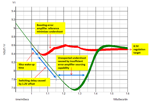
Figure 2 is a comparison between a traditional boost converter and the LM5150-Q1. While the output undershoot using the traditional boost conversion is big and greatly affected by a long wake-up time, a large offset and an insufficient error amplifier sourcing capability, the output undershoot using the LM5150-Q1 is small and minimized. The traditional boost converter’s parameters are set to 1.2V offset, with a 100µA source current limit, a 2mA/V transconductance error amplifier gain and a 50µs wake-up delay.

GUID-4DE7497E-DF79-4A01-BA16-F37BCB9E9739-low.png Figure 2 Pre-boost Output Voltage During Battery Voltage Drop (a Traditional Boost Converter Shown in Green, the LM5150-Q1 Shown in Red)

Conclusion

A pre-boost converter’s output undershoot is affected by device selection. The output undershoot using the LM5150-Q1 is minimized by its small offset, large error amplifier sourcing capability and a quick wake-up time.

Additional Resources