SSZT891 November 2017 MAX3232 , THVD1500
In many industrial and automotive applications, protecting the interface transceivers from all kinds of electrical overstress events is a major concern. Transient voltage suppressor (TVS) diodes are common devices for this purpose, since they can clamp the voltage spikes by generating a low-impedance current path.
The electrical characteristics of TVS diodes are determined by a few process factors. The parameters related to TVS voltage, current and power ratings have a wide variety of values to suit all kinds of applications. But when looking at the component data sheets, it is not always a straightforward selection. In this post, I will discuss voltage parameters and show what kinds of TVS diodes are proper for RS-232, RS-485 and Controller Area Network (CAN) applications. Of course, peak pulse power dissipation and peak impulse current are critical parameters as well, which determine the discharge capability and electrostatic discharge (ESD) level in a system. But here, I’ll focus on the voltage.
TVS Voltage Parameters VWM, VBR and VC
TVS diodes are supposed to act as a clamp when undesired high voltage transients show up. They should also be “transparent” when the transceivers work under normal conditions. Therefore, the first parameter to look at on the data sheet is the rated standoff voltage, VWM. VWM is also known as the rated working voltage, below which the TVS looks like an open circuit with low standby leakage current.
When making a selection, you want VWM to be larger than the recommended operating region of the transceiver. As the incoming voltage goes higher, the TVS starts breaking down and conducting more current at VBR. But what’s even more important is the highest voltage parameter, VC the clamping voltage under a high-current pulse condition. VC represents the maximum clamping voltage with a specific impulse current. When comparing VC to the transceiver parameters, you want to make sure that it doesn’t exceed the absolute maximum voltage ratings of the integrated circuit (IC). The “absolute maximum” is the maximum voltage limit that the transceiver is allowed to see at any time. Any voltage above it would put the transceiver in an unsafe region of operation, and permanent damage could result.
Examples: TVS Selection for RS-232, RS-485 and CAN Transceivers
I’d like to show some examples of RS-232, RS-485 and CAN transceivers and the TVS diodes I would choose for them. I’ve captured the relative parameters from each data sheet, and by looking at the numbers, I think I can give you an idea of how the different components work together.
A popular RS-232 transceiver is TI’s MAX3232, with two transmitters and two receivers. The two key parameters I highlighted in Figure 1 and Figure 2 are the operation voltage of ±5.4V and absolute maximum driver output voltage of ±13.2V, respectively. In the RS-232 standard, the signal swing should above ±5V. Here, you can leave some margin for it.
 Figure 1 MAX3232 Driver Operation
Voltage
 Figure 2 MAX 3232 Driver Absolute
Maximum Ratings
Figure 2 MAX 3232 Driver Absolute
Maximum RatingsA TVS diode that would work for the MAX3232 is the SMBJ8.0CA from Bourns. In Figure 3, you can see that the working peak reverse voltage is 8V and the maximum clamping voltage is 13.6V.
 Figure 3 SMBJ8.0CA Working Peak Reverse Voltage and Maximum Clamping Voltage
Now, let’s look at an 8-pin RS-485 transceiver, TI’s THVD1500. RS-485 transceivers can work with a wide common-mode range (-7V to 12V) per the RS-485 standard (Figure 3). As shown in Figure 4, the absolute maximum voltage of the bus pins is ±18V for the THVD1500.
 Figure 4 THVD1500 Driver Operation
Voltage
 Figure 5 THVD1500 Driver Absolute
Maximum Ratings
Figure 5 THVD1500 Driver Absolute
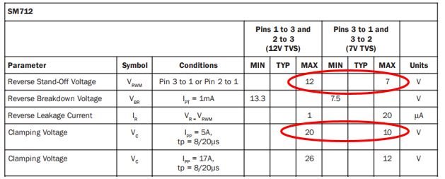
Maximum RatingsA common TVS diode for RS-485 applications is the SM712. This TVS has asymmetrical reverse stand-off voltages to match the common-mode operating range of an RS-485 application. Also, its clamping voltage is close to the limit of the TI THVD1500, as seen in Figure 6.
 Figure 6 SM712 Reverse Stand-Off Voltage and Clamping Voltage
Last but not least, the TI SN65HVD1040A 8-pin CAN transceiver has a pretty high absolute maximum voltage (Figure 7), which makes TVS selection easier. Similar to RS-485, CAN buses can tolerate some common-mode voltage variation as well (Figure 8).
 Figure 7 SN65HVD1040A Driver Absolute Maximum Ratings
 Figure 8 SN65HVD1040A Driver Operation Voltage
Combining all factors, the CDSOT23-T24CAN from Bourns could be one of the choices for the SN65HVD1040A. This device offers a reserve working voltage of 24V and clamping voltages from 36V to 40V. To save space, I haven’t copied the data sheet here. But I believe it would not be too hard to find the parameters given the previous two examples.
Again, voltage parameters are only part of the electrical characteristics of TVS devices, although they are the first things to look at for TVS selection. To get a better understanding of the full characteristics of a TVS device, you can also look at other parameters such as peak power and peak current.
Additional Resources:
- Michael Peffers’ blog post, “How to protect CAN bus transceivers from ESD and transients,” has more details about using the SM712 to protect CAN transceivers and includes information about the international Electrotechnical Commission (IEC) 61000-4-2 ESD standard
- Click here to learn how to protect CAN bus transceivers from ESD and transients
- Check out High EMC Immunity RS-485 Interface Reference Design for Absolute Encoders and Universal Digital Interface to Absolute Position Encoders Reference Design
- Learn more about CAN/LIN, RS-485/RS-422 and RS-232 transceivers