SSZTBL5 February 2016 LMG5200
Today’s blog post is a hands-on project: You’re going to dim a lamp with a gallium nitride (GaN) power stage, a Hercules™ microcontroller and a scroll wheel. I’ll cover both hardware and firmware. Be prepared to fire up your soldering equipment.
You can control GaN power stages in a number of ways. The TI user guide for the LMG5200 GaN half-bridge power stage uses a combination of passive components and discrete logic gates. In this post, I’ll describe how to drive it with a Hercules microcontroller. Figure 1 shows the Hercules modules that you’ll use to drive the LMG5200.
 Figure 1 Hercules PWM Modules with Dead
Band Generator
Figure 1 Hercules PWM Modules with Dead
Band GeneratorGaN and Hercules power stages are a perfect match. Both play well in industrial and automotive applications. The Hercules pulse-width modulation (PWM) module has specialized hardware to drive these signals. The deadband generator (DB) submodule is perfectly suited to generate the dead time that you need.
Setup
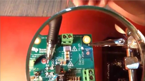
Figure 2 shows the hardware modules that you’ll connect together. The load is a classic light bulb. A Texas Instruments LMG5200 GaN evaluation kit controls the power going to the lamp. The scroll wheel of an old mouse serves as the input. You’re going to use that to wick the output of the GaN power stage up and down.
 Figure 2 Hardware Setup
The Hercules LaunchPad will glue the components together. When you rotate the scroll wheel, it will make the lamp shine brighter or dimmer.
Design
It isn’t difficult to come up with a clean hardware structure because you have clear functional blocks (Figure 3). There’s the logic part: the Hercules controller with its input (scroll wheel) and output (GaN driver), and the power regulation: the GaN driver with input (LaunchPad) and output (the lamp).
 Figure 3 Hardware Modules
The same is true for the firmware. A state machine manages the functionality, and there are two modules: a rotary function that listens to the scroll wheel and a GaN module that talks to the LMG5200. Both modules rely on the low-level Hercules peripheral drivers (Figure 4).
 Figure 4 Firmware Modules
Activities
Let’s start with the output side. The first step is to generate the right PWM signals on the LaunchPad to control the GaN driver. Next, connect the GaN evaluation kit to the LaunchPad, making some changes to the PCB along the way. Finally, plug in the input. Turn the mouse scroll wheel into a stable quadrature encoder and integrate the signals into the firmware.
Driving the LMG5200 GaN Power Stage the Right Way
The LMG5200 GaN half-bridge power stage has particular requirements for its input signals. I covered these signals in depth in a previous post. The key is to create two inverse PWM signals. A pause is also required at a particular point. When your signal switches logic levels, you will have to wait a short time (called dead time) between the switch-low of one and the switch-high of the other.
When the low signal is high, the high signal should be low, and vice versa. But you will have to inject a small delay between the falling edges of one signal and the rising edge of the other. Both signals will be low for a few nanoseconds.
 Figure 5 LMG5200 Input Signal with Dead
Time
Figure 5 LMG5200 Input Signal with Dead
TimeIn Figure 5, the dead time is the hatched area between the falling and rising edges. Let’s compare it to Figure 6, which captures the signal generated with the Hercules microcontroller.
 Figure 6 Capture of the Hercules PWM and Dead Time
The yellow and blue traces in Figure 6 are the low and high signals coming out of the Hercules ePWM module. The purple trace is a calculated signal (yellow and blue) and represents the dead time.
Your oscilloscope’s SUM function is a big help here. You can use it to measure the width of the dead time (the 0V dip where both signals are low). Equally important, it will show you if you accidentally drive both signals high at the same time (a condition that would destroy your GaN device) as a 10V peak.
Set up the PWM Signals
You can configure the Hercules microcontroller and its modules with HALCoGen, the visual hardware configurator. Enable the peripherals that you require, parameterize them, and let HALCoGen generate your project. You get a compile-able project with full source code, and you’ll only have to add two lines of code to get a running design.
First, enable the ePWM driver. That’s the peripheral that will generate the two signals that you’ll send to the GaN integrated circuit (IC).
 Figure 7 Enable PWM
Next, activate one of the available PWM modules and create the signals that the LMG5200 GaN half-bridge needs.
 Figure 8 Activate PWM Module 1
You can configure the whole signal, including dead time, on a single screen. By setting the check boxes and values to those shown in Figure 9, your ePWM module will be ready to output the GaN signals.
 Figure 9 Configure PWM Signal and Dead
Time
Figure 9 Configure PWM Signal and Dead
TimeI wrote a blog post on element14 that explains each of the settings, and how this configuration gives you the perfect signal for the LMG5200.
Let HALCoGen generate the project source for you, and add these lines to the main() function:
etpwmInit(); // apply and activate the HALCoGen configuration
while(1){
}
You can build and execute this project using Code Composer Studio™ software, and the LaunchPad is ready. Probe the ePWM signals, and you’ll get a similar image as the scope capture in Figure 6. The duty cycle will be 10% and the frequency 1MHz.
And that’s it. You’ve turned the LaunchPad into a device that can control the GaN driver straight away. In the next installment of this series, I’ll explain how to connect the GaN evaluation kit.