SSZTC50 september 2015 ADC12J2700
Introduction
Designers of data-acquisition systems – especially for precision measurements in process control or automation systems – have routinely designed their systems to operate in the first Nyquist zone, which simply means that the maximum input frequency must be limited to less than one-half the sampling frequency. So if you build a system to capture audio at a maximum of 20KHz, then you must sample at more than 40KHz to ensure that you capture the highest-frequency components.
Aliasing
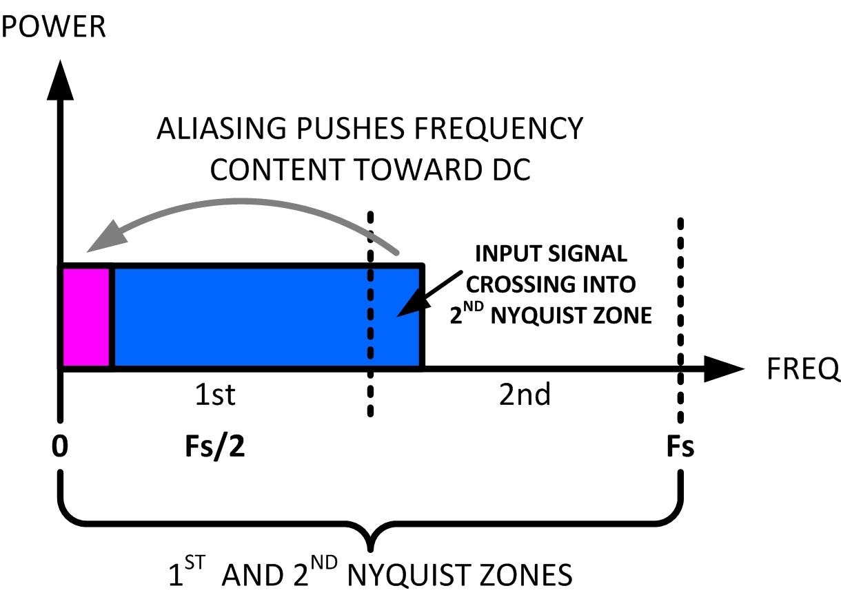
So what happens to a system when you don’t obey the rules? Let’s say that you sample the analog signal at 15kHz with frequency components up to 20kHz – you’ll wind up with “aliasing” or folding of the upper components into the input signal’s operating band (see Figure 1). These aliased signals will add to the original signal and there will be no way to discriminate the aliased frequency components from the original signal.
 Figure 1 The Input Signal Crosses into
the Second Nyquist Zone and Is Aliased into the Signal’s Operating Band
Figure 1 The Input Signal Crosses into
the Second Nyquist Zone and Is Aliased into the Signal’s Operating BandIn most cases, a system that captures analog signals and doesn’t follow the Nyquist sampling rule is considered “bad” and requires an anti-aliasing filter before the analog-to-digital converter’s (ADC’s) input to prevent frequency components from crossing into the upper Nyquist zones. Sometimes, however, it’s a good thing.
In radio frequency (RF) systems that operate in extremely high-frequency modes, the amount of data moved between a processor (or a field-programmable gate array [FPGA]) and the data converter can be incredible – especially when the system is operating in the first Nyquist zone (or simply “the first Nyquist”). For instance, a digital-to-analog converter (DAC) running in the first Nyquist for a 1GHz output frequency would need to clock the output at over 2GHz to achieve the desired frequency content.
This also applies to ADCs – if the input from the RF subsystem has an operating band between 900MHz and 1GHz, then the ADC must sample at over 2GHz to place all of the frequency content in the first Nyquist.
Using Nyquist Aliasing as Benefit
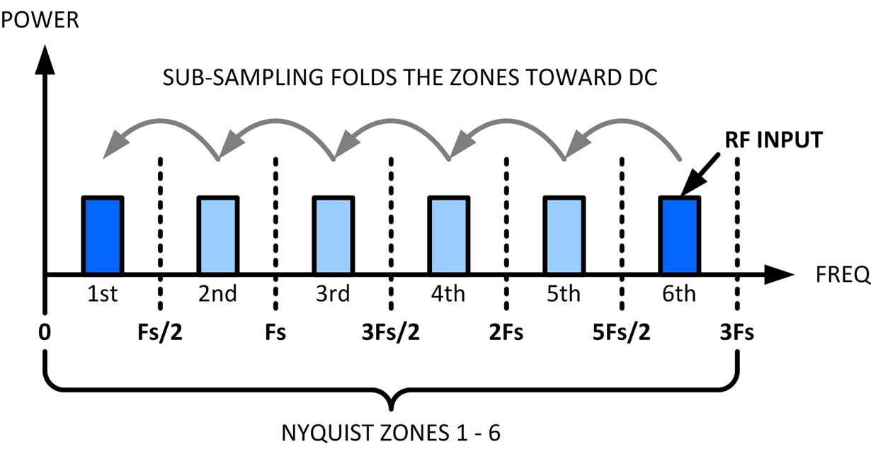
The trick is to use the aliasing (or frequency folding) to your advantage. By undersampling the data converter, higher-frequency content will be aliased into all of the lower Nyquist zones (see Figure 2). You will need to make absolutely sure that nothing ends up in the lower bands – any noise or frequency components in the lower zones will also be aliased into the first Nyquist. The good news is that the data rate from the data converter is only a fraction of the required RF input sample rate if this were a first Nyquist system. Under sampling greatly reduces the data rate of the samples supplied to the digital signal processor (DSP) or FPGA.
 Figure 2 Higher-order Frequency
Components Are Folded into the Lower Nyquist Zones When Subsampling
Figure 2 Higher-order Frequency
Components Are Folded into the Lower Nyquist Zones When SubsamplingThe ADC’s only major requirement is that the input bandwidth must be sufficient for the input frequency or else the signal will be distorted. For example, the ADC12J2700 can sample up to 2.7GSPS, but it has an input bandwidth greater than 3GHz, allowing input signals beyond the maximum sample rate and thus folding them into the lower zones. There are some additional considerations that are beyond the scope of this post, but in general this trick can save you from dealing with extremely high data rates and processing requirements.
If you’re architecting a high-performance digital RF system, you may want to consider using this method in conjunction with the proper DAC or ADC. When correctly designed, this method can greatly simplify the processing and data-flow requirements of these systems.
Additional Resources
- Read the Analog Wire blog post, “Aliasing in ADCs: Not all signals are what they appear to be.”
- Learn more about RF sampling and how aliasing can be your friend in this blog post.
- Find more than 100 data-converter technical resources in our Data Converter Learning Center.
- Read TI’s white paper, “Why Use Oversampling when Undersampling Can Do the Job?”
- Learn more about the ADC12J2700.
- Learn about TI’s data converter portfolio and find technical resources.