SSZTC70 september 2015 UCC27524A , UCD3138
While MOSFET/IGBT gate drivers are designed to drive capacitive loads at high frequencies with high peak currents of short duration, did you know that they can also drive inductive loads, such as power-relay coils? That’s the secret life of a MOSFET/IGBT gate driver. This is not new concept. As they drive the inductive loads, they typically switch at much lower frequencies with drive currents limited by the coil resistance. Gate-drive ICs are already used to drive inductive loads such as gate-drive transformers, but at frequencies in the range of tens to hundreds of kilohertz.
With the increased use of power relays in automotive and industrial applications such as domestic electricity e-metering and smart grids, there is a need to be able to control high-power relays from microcontrollers. There are certain challenges towards doing this, all of which can be easily addressed by employing a gate driver. We’ll talk about how gate driver devices can be used to control relays in this blog post.
Relay coils require much higher currents and voltages than a microcontroller can supply. In addition to providing power, it is also necessary to provide some form of level shift in terms of voltage to enable the microprocessor to control a high-power relay in applications such as e-metering.
The main function of a high-power latching relay is to safely connect and disconnect the power.
 Figure 1 Single-phase E-meter
The UCC27524A is a dual-channel gate driver originally designed to drive capacitive loads in the form of MOSFETs and IGBTs. The device is capable of sourcing and sinking up to 5A peak for short periods. The Vdd range is 4.5V to 18V, allowing it to cover applications that use a 12V or 15V relay drive. The input pin thresholds are based on TTL (transistor–transistor logic) and CMOS (complementary metal-oxide semiconductor)-compatible low-voltage logic, which is fixed and independent of the supply-rail voltage. This allows direct interface to a microprocessor, and provides necessary level shift to drive the relay.
Let’s look at how you can use the UCC27524A to drive a dual-coil latching relay like the K100. See Figure 2 & 3 for circuit details
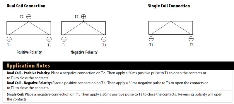
 Figure 2 Simplified Schematic for Dual
Coil Configuration Drive Circuit
Figure 2 Simplified Schematic for Dual
Coil Configuration Drive Circuit Figure 3 Dual-coil Configuration for a
Latching Relay in E-metering Applications
Figure 3 Dual-coil Configuration for a
Latching Relay in E-metering ApplicationsI rigged up a simple test circuit to provide a 100ms-wide pulse to trigger the latching relay using the UCC25724A gate driver (Figure 4).

 Figure 4 Test Circuit
 Figure 5 Waveforms for Latching-relay
Drive
Figure 5 Waveforms for Latching-relay
DriveRelay drives operate at low frequencies (sub 1Hz), with 20ms to 200ms durations like the waveforms shown in Figure 5 & 7. The coil resistance limits the peak current, and the operating voltage power dissipation is unlikely to be a concern. In addition, many gate-driver ICs are available with thermal-pad thermal management such as the MSOP-8 PowerPAD™ package.
The same concept applies to a single-coil latching relay:

 Figure 6 Simplified Schematic for
Single Coil Configuration Drive Circuit
Figure 6 Simplified Schematic for
Single Coil Configuration Drive Circuit Figure 7 Single-coil Configuration
Waveforms
Figure 7 Single-coil Configuration
WaveformsThat’s all there is to it: simplifying relay drive from microcontrollers using a MOSFET/IGBT gate driver. What alternative applications do you use MOSFET gate drivers for?
Additional Resources:
- Take a look at the UCD3138 digital resonant LLC converter evaluation module.
- Learn more about the UCC27524A MOSFET driver
- Simulate your UCC27524A design using PSpice and TINA-TI models