SSZTCE9 July 2015 SN65HVD24 , SN75176B
As many of you know, RS-485 is a physical layer standard used in all kinds of industrial and military standards. My colleague has a good series on RS-485 Basics on the Industrial Strength blog. In this post, I’ll touch on the basics from a little different angle and talk about how to get more range and speed from an RS-485 design.
RS-485 uses a differential pair of wires to allow a multiple-input, multiple-output (MIMO) configuration limited by upper-layer protocols residing in software. It is generally limited to 4,000 feet (about 1,200 meters) of cable and a maximum transmission speed of 10Kbps.
Assuming a single point-to-point model, the problem with going farther or faster (other than the driver/receiver limits) is the insertion loss of the cable. This is a function of length, cable inductance and dielectric loss. In general, the insertion loss appears as a low-pass filter and for many shielded twisted-pair cables used in harsh industrial environments will have roughly 2dB roll-off around 1MHz (per 100 meters) and 6dB roll-off at 10MHz (per 100 meters).
For a “bit” to be detectable without excessive jitter, edge transitions need to be fast and clean. If you perform a Fourier series on a square wave (a “101010 …” pattern of bits), you’ll see components that are appreciable well past the 11th harmonic. The insertion loss of 300 meters of cable will attenuate the higher frequencies, resulting in distortion.
If you try to use a standard RS-485 transceiver that can operate at 10Mbps (such as the SN75176B) to drive 300 meters of shielded twisted-pair cable, the high-frequency attenuation will slow the edge transitions, smearing the signal. At the receiver input, the signal will be greatly distorted from what was actually transmitted by the driver. Due to this distortion, there is uncertainty in when the receiver will detect an edge transition resulting in excessive jitter on the receiver’s output.
The typical ways to combat this problem are to equalize (or add an inverse loss function) before the receiver stage or pre-distort the driver output. Equalization circuitry adds gain at specific frequencies to flatten the cable’s transmission characteristics, resulting in an approximate flat response over the length of the cable. The loss function varies with cable type and distance, so you must adjust the amount of equalization – either by fixed values or dynamically through adaptive equalization. Pre-distortion (also called emphasis) either attenuates the lower frequencies (de-emphasis) or provides gain at the higher frequencies (pre-emphasis). This has a similar effect as equalization to flatten the cable response at the receiver.
Equalization and/or pre-distortion circuitry are prevalent in very high-speed (gigabit) transceivers, but rarely found in slower communication standards such as RS-485. However, TI has several extended-performance RS-485 transceivers such as the SN65HVD2x family (including the SN65HVD24). This family has several devices with built-in equalization on the receiver side of the transceiver.
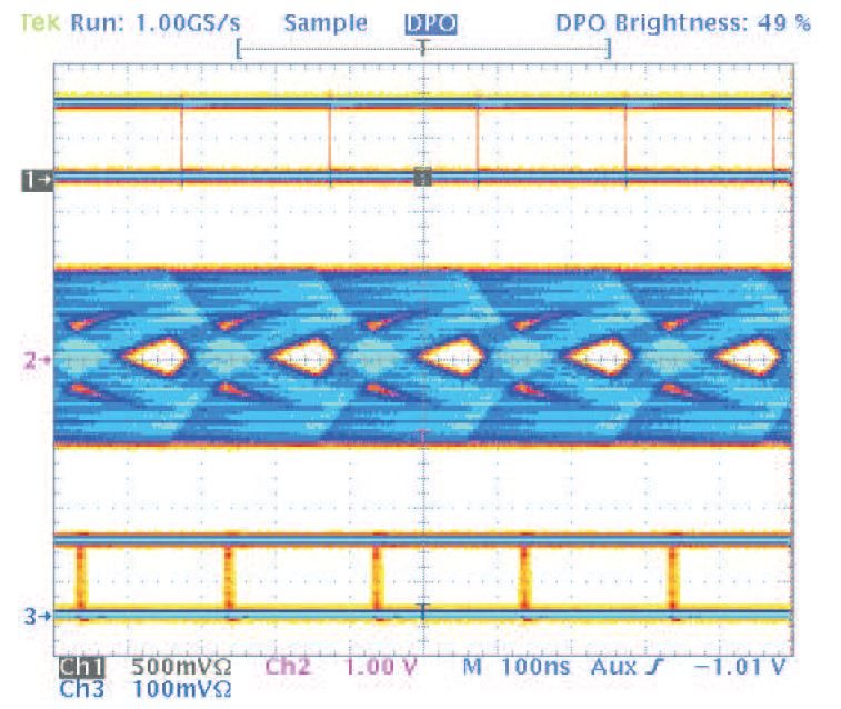
Figure 1 shows a 5Mbps non-return to zero (NRZ) pseudo-random data pattern over 500 meters of twisted-pair wire. Trace 1 is the output of the driver stage, trace 2 is the signal at the input to the receiver after 500 meters of cable and trace 3 is the receiver output.
 Figure 1 SN65HVD24 Receiver Performance at
5Mbps over 500 Meters of Twisted-pair Cable
Figure 1 SN65HVD24 Receiver Performance at
5Mbps over 500 Meters of Twisted-pair CableRS-485 transmission over larger distances and higher data rates is possible when using components that include circuitry to compensate for the cable losses. A great application note that goes into greater detail is “Use Receiver Equalization to Extend RS-485 Data Communications” by Clark Kinnaird. And if you’re trying to go faster and farther over RS-485, you might take a look at the SN65HVD2x transceiver devices.
Additional Resources
- Find out more about TI’s RS-485 transceiver portfolio.
- Read blog posts about RS-485 transceivers.
- Check out our Half-Duplex, Non-Isolated RS-485 BoosterPack TI Design reference design.