SSZTCJ6 june 2015 CSD17570Q5B , CSD17579Q5A
Welcome back, fellow FET enthusiasts to part four of the "Understanding MOSFET Data Sheets" blog series! Today I’ll be talking about pulsed current ratings, how they are calculated, and how they are represented in the safe operating area graph on the FET datasheet.
The pulsed current rating (IDM) that appears on the front page of the datasheet, is not unlike the continuous current rating, in that it is a theoretically calculated value. However, unlike the continuous current, the IDM is only calculated as a function of thermal constraints, from normalizing RθJC to the given pulse duration and duty cycle specified in the footnote of the “Absolute Maximum Ratings” table.
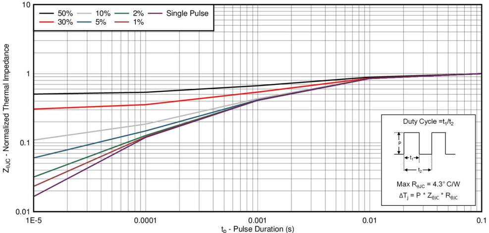
Take for instance, the recently released CSD17579Q5A 30V N-Channel MOSFET. The data sheet for this part has a maximum pulsed current rating of 105A, based on the conditions that the pulse duration is less than or equal to 100µs and the duty cycle is less than or equal to 1%. To determine the transient thermal impedance to use in calculating the IDM, we will refer to the normalized thermal impedance curve, shown in Figure 1 below. If we look at the 1% duty cycle (brown) line at 100µs, we get a normalization factor of 0.12, which we will use to calculate the max power and thereby current the device can handle for this duration and duty cycle. This value is given by 0.12 multiplied by the max DC RθJC (4.3˚C/W), yielding a transient ZθJC of 0.52˚C/W.
 Figure 1 CSD17579Q5A Normalized Transient Thermal
Impedance Curve
Figure 1 CSD17579Q5A Normalized Transient Thermal
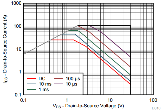
Impedance CurveUsing this value for thermal impedance and calculating the max current just as we did for its continuous counterpart, we will calculate a thermally limited current of 119A. But wait! The datasheet said 105A! So what gives? If you look at the SOA of the device, shown below in Figure 2, it can be seen that the 100us line actually bumps into the RDS(ON) limitation before it can get to 119A. This intersection occurs at 105A. So in cases like this, we will retroactively derate the absolute maximum pulsed current as the physical limitations of the device’s RDS(ON) will limit the device from being able to reach its thermal limitation.
 Figure 2 CSD17579Q5A Safe Operating Area
Current limitations are calculated for each greater pulse appearing in the SOA, and provided they don’t run into the RDS(ON) limitation first, this value is where those curves are capped.
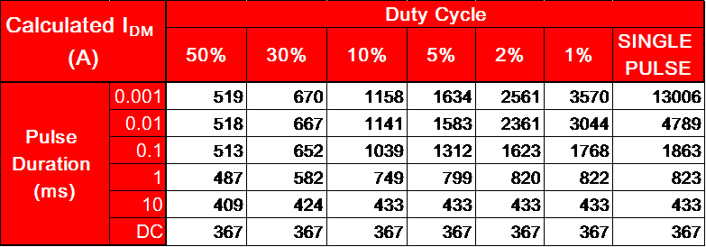
Because the absolute maximum current is entirely theoretical, prior to release of the part we will attempt to get some hard data to further convince ourselves that the part is capable of handling this much power. Unfortunately, our best boards and testers are only capable of pulsing the devices up to 400A, which is why that value has served as an artificial cap for all devices we release. Some vendors have a similar cap, while others do not limit themselves in such a manner. While you will never see TI rate a FET beyond 400A IDM, either on the front page or in the SOA, Figure 3 below shows you how ridiculously high the theoretical pulsed current rating can get, in this case for the CSD17570Q5B, a part with very low RDS(ON) (0.69mΩ max) and thermal impedance (0.8˚C/W). This demonstrates how different vendors can get away with displaying higher ratings, if they play with features such as pulse duration and ignore practical limitations of testing the device.
 Figure 3 CSD17570Q5B Calculated Pulsed
Currents
Figure 3 CSD17570Q5B Calculated Pulsed
CurrentsIn part five of “Understanding MOSFET data sheets,” I will provide a similar analysis for the pulsed current rating, IDM, and show how this ties into the other parameters on the datasheet, including the SOA. In the meantime, watch a video "NexFET™:Lowest Rdson 80 and 100V TO-220 MOSFETs in the World" and consider one of TI’s NexFET power MOSFET products for your next design.