SSZTCX2 March 2023 MCF8315A , MCF8316A , MCT8316A , MCT8329A
With the emergence of open-concept floor plans for homes and offices and the shift to hybrid electric vehicles and electric vehicles, demand for quieter and more efficient motor control is increasing significantly. Even the smallest differences in acoustics can make a big difference in audible noise.
In Figure 1, you can see how appliances in a living space contribute to overall noise levels. Advanced real-time control techniques can help you achieve better acoustic performance for your systems, including motor control circuitry with higher power density, more integration, and more efficient systems. Some additional strategies include vector field-oriented control (FOC) algorithms using continuous pulse-width modulation (PWM), specific control algorithms to reduce vibrations, and integrated control to apply dead-time compensation and PWM generation to reduce audible noise.
 Figure 1 Audible noise in an open
concept kitchen and living room
Figure 1 Audible noise in an open
concept kitchen and living roomWith all of these different products and strategies to reduce audible noise in motion control applications, it may be difficult to know which strategy is best for your application. In this article, I’ll list the top three ways to reduce audible noise in motion control applications, using BLDC integrated control gate drivers as examples.
PWM
The first strategy in reducing audible noise in motion control applications is continuous PWM. PWM is a technique that generates output waveforms by turning transistors on and off, resulting in the motor voltage being high or low at any given time. The inductance in the motor then filters these waveforms to essentially average the output waveform. Adjusting the duty cycle (the ratio of the time the waveform is on compared to the time it is off) will change the average voltage. Figure 2 illustrates an example of sinewave generation using PWM.
 Figure 2 Example sinewave generation
using PWM
Figure 2 Example sinewave generation
using PWMFor example, TI’s MCF8315A BLDC integrated control gate driver, a sensorless FOC motor driver, implements continuous and discontinuous space-vector PWM schemes. Continuous modulation helps reduce current ripple for motors with low inductance, but results in higher switching losses because all three phases are switching. Discontinuous modulation has lower switching losses (because there are only two phases switching at a time) but higher current ripple. In Figure 3 and Figure 4, you can see the differences between continuous and discontinuous PWM.
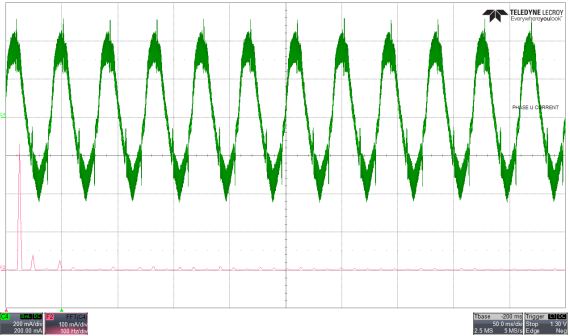 Figure 3 Phase-current waveform and
fast Fourier transform (FFT) discontinuous PWM
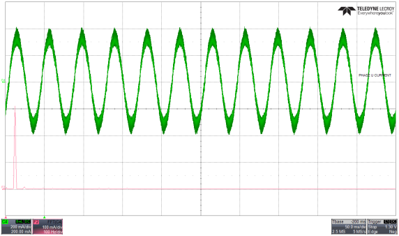 Figure 4 Phase-current waveform and FFT
continuous PWM
Figure 4 Phase-current waveform and FFT
continuous PWMDead-time compensation
The second strategy used to reduce audible noise in motion control applications is dead-time compensation. In motor control applications, inserting dead time between the switching of the high- and low-side metal-oxide semiconductor field-effect transistors in a half bridge can avoid a shoot-through condition. After inserting dead time, the expected voltage and applied voltage at the phase node will differ, and the phase-node voltage introduces unwanted distortion in the phase current, causing audible noise.
To manage this additional noise, engineers can integrate dead-time compensation using a resonant controller to control the harmonic component in the phase current, alleviating the current distortion caused by the dead time, as shown in Figure 5.
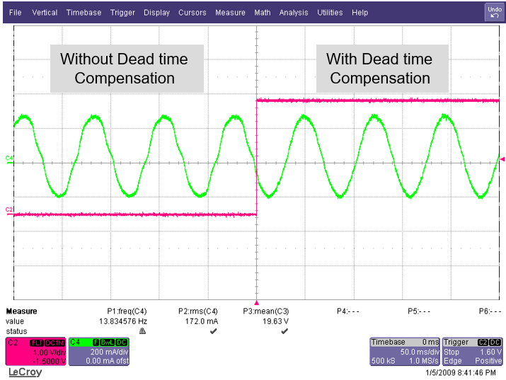 Figure 5 Sensorless FOC dead-time
compensation analysis
Figure 5 Sensorless FOC dead-time
compensation analysisFor example, TI’s MCF8316A BLDC integrated control gate driver, a sensorless FOC motor driver, uses this built in feature to optimize acoustics across multiple electrical speeds as shown in Figure 6.
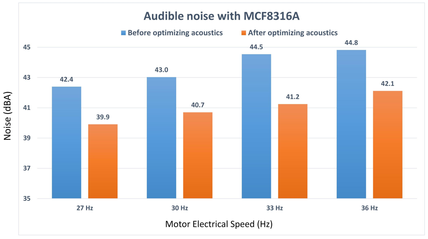 Figure 6 PWM modulation and dead-time
compensation implemented to optimize MCF8316A acoustics
Figure 6 PWM modulation and dead-time
compensation implemented to optimize MCF8316A acousticsVariable commutation modes
The last technique for reducing audible noise in motion control applications is variable commutation modes. In trapezoidal commutation, there are two main configurations: 120 degrees and 150 degrees. Trapezoidal 120 degrees may result in more acoustic noise because the long high-impedance period causes increased torque ripple; see Figure 7 and Figure 8. And trapezoidal 150 degrees can only operate at low speeds, given the small window for detecting the zero crossing.
To combat these challenges and improve acoustic performance, engineers can build motor driver systems that can dynamically switch between trapezoidal 120 degrees and trapezoidal 150 degrees. This dynamic modulation can improve overall acoustic performance during BLDC motor control.
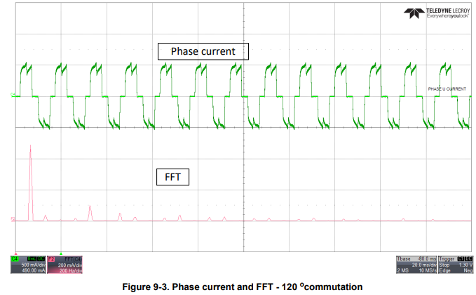 Figure 7 Phase current and FFT – 120-degree commutation
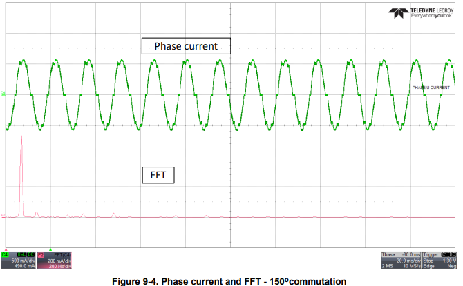 Figure 8 Phase current and FFT – 150-degree commutation
For example, TI’s sensorless BLDC integrated trapezoidal control gate drivers, like MCT8329 and MCT8316, use this built in feature to optimize acoustics across multiple electrical speeds as shown in Figure 9.
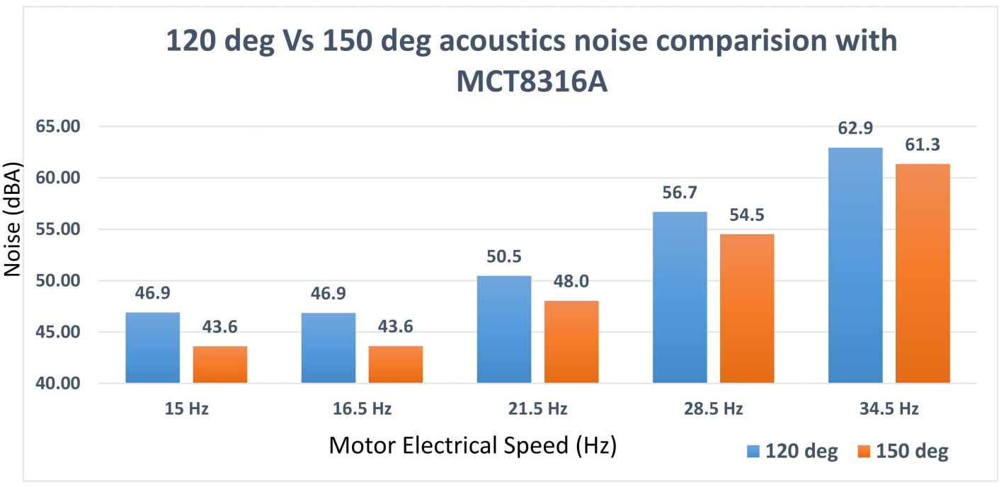 Figure 9 Variable commutation modes
with dynamic modulation implemented to optimize MCT8316A acoustics
Figure 9 Variable commutation modes
with dynamic modulation implemented to optimize MCT8316A acousticsConclusion
TI is investing in motion control technologies to help build more efficient and acoustic-sensitive systems, with building blocks designed to meet acoustic requirements. When designing your system, keep in mind these top three ways to reduce audible noise in motion control applications.
Additional resources
- Check out the application report on “How to Reduce Motor Noise with Code-Free, Sensorless BLDC Motor Drivers” or the video, “Reduce audible motor noise with BLDC motor drivers.”
- Learn more about TI’s integrated control BLDC drivers, BLDC motor drivers, Arm®-based processors, C2000™ real-time microcontrollers and MSP430™ microcontrollers.
- Read the application brief, "High-Efficiency , Code-Free Sensorless BLDC Motor Drives for Scalable Systems."