TIDA035 October 2020
4.2 Input bias current
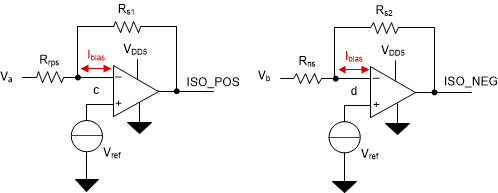
In the above calculations it is assumed that the input impedance is infinite and there is no current flowing into the inverting input (–). But actually a small amount of current must flow into the inputs due to bias requirement or parasitic leakage in real op-amp. The input bias current can either flow into or out of the inputs.
 Figure 4-1 Input Bias Current Flows into
or out of Inverting Input
Figure 4-1 Input Bias Current Flows into
or out of Inverting InputIf the input bias current is considered in Equation 2 and Equation 5, they can be revised as follows:
Equation 11. 

Equation 12. 

Then ISO_POS and ISO_NEG can be obtained including input bias current error respectively.
Equation 13. 

Equation 14. 
