TIDT331 august 2023
3.2 Load Transients
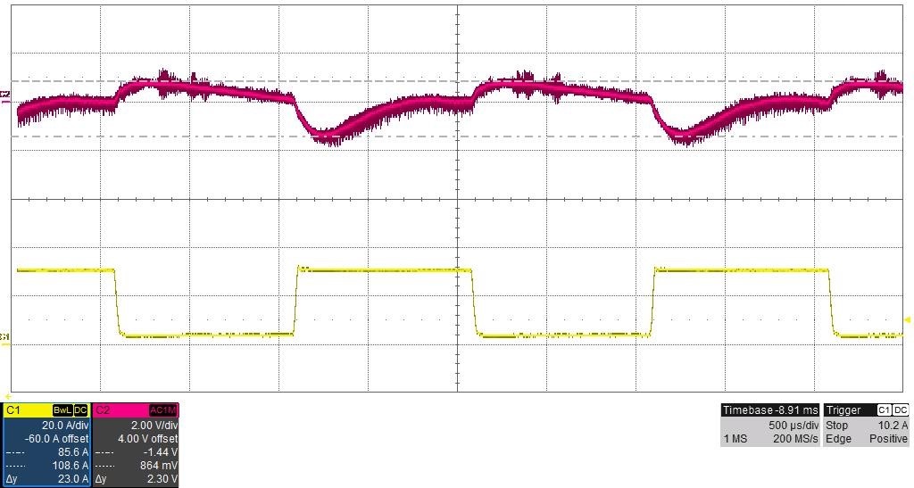
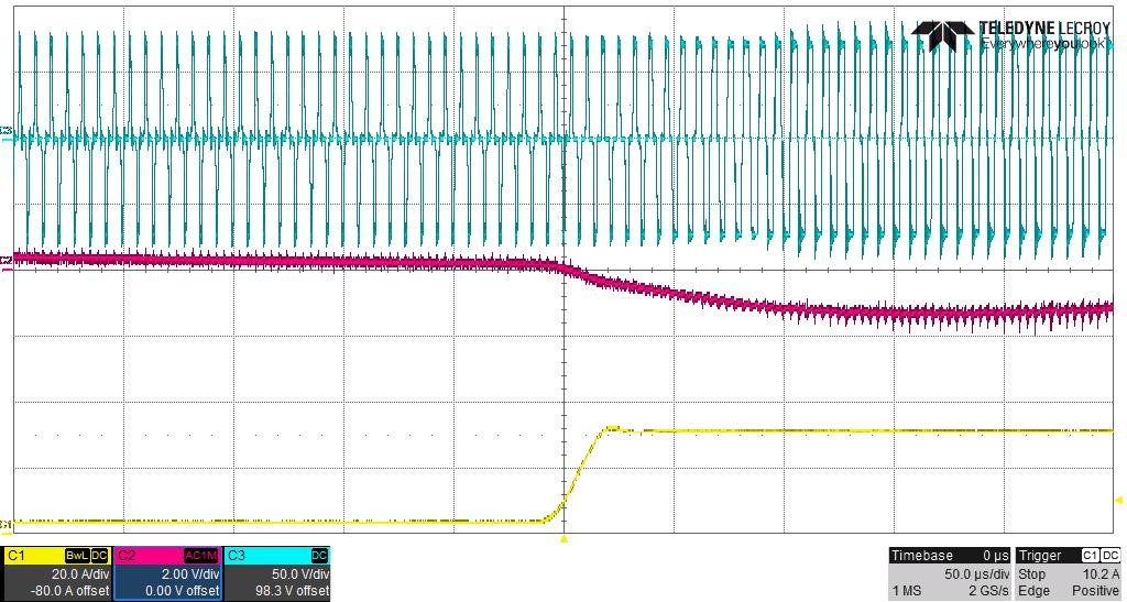
The waveforms illustrated in Figure 3-2 and Figure 3-3 represent the transient response of PMP22951 for a 3-A to 31-A load step. The test is conducted according to M-CRPS version 1.00, release candidate 4, table 7-5. 1 mF is connected across the output terminals. The load current slew rate is 1 A/µs.
C1 = Load Current, C2 = VOUT, AC coupled, C4 = Secondary Winding Voltage
 Figure 3-2 PMP22951 Transient Response for a 3-A to 31-A Load Step
 Figure 3-3 PMP22951 Transient Response for a 3-A to 31-A Load Step (Zoomed-In
View)