TIDT337 may 2023
3.1 Output Current Ripple
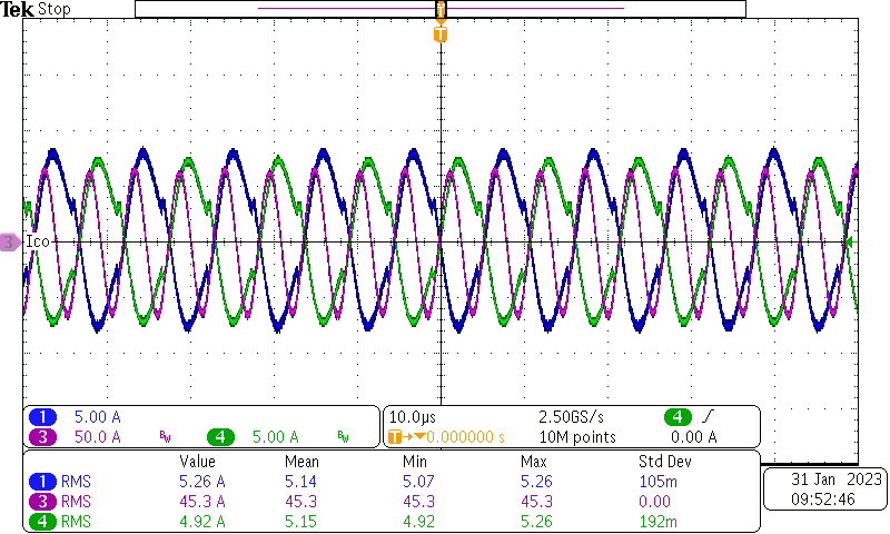
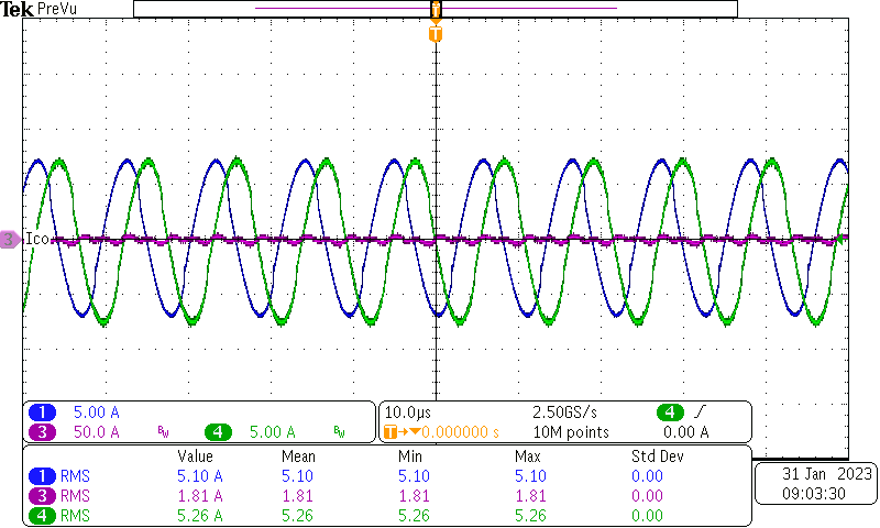
The ripple current of this design was tested on the output capacitors with different phase shifting. The following list shows the primary current of each phase and the ripple current in output capacitors, with 0 degree shift and 90 degree shift.
- Channel 1, is the primary current of phase A
- Channel 4, is the primary current of phase B
- Channel 3, is the ripple current on the output capacitors
 Figure 3-1 Waveform With 0 Degree Shift
at133-A Load
 Figure 3-2 Waveform With 90 Degree Shift
at 133-A Load