TIDUEY3 November   2020


  1.   Description
  2.   Resources
  3.   Features
  4.   Applications
  5.   5
  6. 1System Description
  7. 2System Overview
    1. 2.1 Block Diagram
      1. 2.1.1 Hardware Block Diagram
      2. 2.1.2 Software Block Diagram
        1. 2.1.2.1 mmWave SDK Software Block Diagram
        2. 2.1.2.2 Software Block Diagram of Application
    2. 2.2 Highlighted Products
      1. 2.2.1 AWR6843AOP
      2. 2.2.2 mmWave SDK
    3. 2.3 System Design Theory
      1. 2.3.1 Use-Case Geometry and Sensor Considerations
      2. 2.3.2 Low-Level Processing
      3. 2.3.3 High-Level Processing Details
        1. 2.3.3.1 DPM Model
        2. 2.3.3.2 Occupancy Detection State Machine
      4. 2.3.4 Output Through UART
  8. 3Hardware, Software, Testing Requirements, and Test Results
    1. 3.1 Required Hardware and Software
      1. 3.1.1 Hardware
      2. 3.1.2 Software
    2. 3.2 Testing and Results
      1. 3.2.1 Test Setup
      2. 3.2.2 Test Results
  9. 4Design Files
    1. 4.1 Schematics
    2. 4.2 Bill of Materials
    3. 4.3 Altium Project
  10. 5Software Files
  11. 6Related Documentation
    1. 6.1 Trademarks

Hardware

The in-cabin sensing application runs on the AWR6843AOP EVM and connects to a visualization tool running on a PC via USB. For details regarding usage of this board, see the AWR6843 Evaluation Module (AWR6843ISKM) Single-Chip mmWave Sensing Solution.

The AWR6843 core design includes:

  • AWR6843 device: A single-chip, 60-GHz radar device with an integrated DSP
  • Power management network using a low-dropout linear regulator (LDO) and power management integrated circuit (PMIC) DC/DC supply (TPS7A88, TPS7A8101-Q1, and LP87524B-Q1)
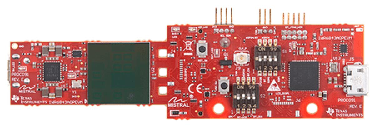
GUID-F46FDDD6-5F1F-4894-A9C9-95ECDCC413C1-low.jpg Figure 3-1 AWR6843 Intelligent mmWave Sensor Antenna-On-Package (AoP) Evaluation Module Board Image