SLYA024A December 2017 – September 2021 INA2180 , INA2180-Q1 , INA2181 , INA2181-Q1 , INA4180 , INA4180-Q1 , INA4181 , INA4181-Q1
As the need for system intelligence and power efficiency continues to grow, the need for better monitoring of critical system currents is increasingly paramount. In the past this may have been done with multiple operational amplifiers configured as difference amplifiers or multiple current sense amplifiers distributed within the system. As the number of current monitor channels increases so does the amount of external components needed to realize a solution. The added components increase the design complexity and solution size, and can degrade the overall current sensing accuracy.
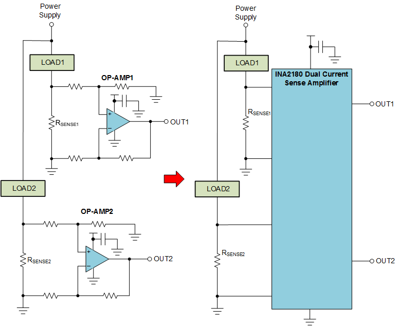
For example, consider the case where two currents need to be measured as shown in Figure 1-1.
 Figure 1-1 Discrete vs. Integrated Current Sensing Solutions
In this case, the operational amplifier-based solution requires 8 resistors to set the gain, 2 bypass capacitors and 2 current sense resistors. The same circuit implemented with an INA2180 only requires the 2 current sense resistors and a single bypass capacitor. Since the integrated gain-set resistors are well matched, the accuracy of the INA2180 solution is much better than what can be achieved in a cost effective discrete implementation. The integrated gain-set resistors permit higher accuracy monitoring or allow use of a cheaper wider tolerance current sense resistor. The INA2180, INA2181, and INA2290 devices are also more flexible in that they can monitor voltage drops across resistors that have voltages greater than the supply voltage.
In addition to simplifying the design process and reducing the number of external components, having multiple current monitoring devices in a single package facilities several common application solutions.
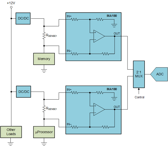
For example, consider the application shown in Figure 1-2, where the total current drawn by the memory and processor is monitored by an external ADC.
 Figure 1-2 Monitoring Total Current in Two Supply Rails
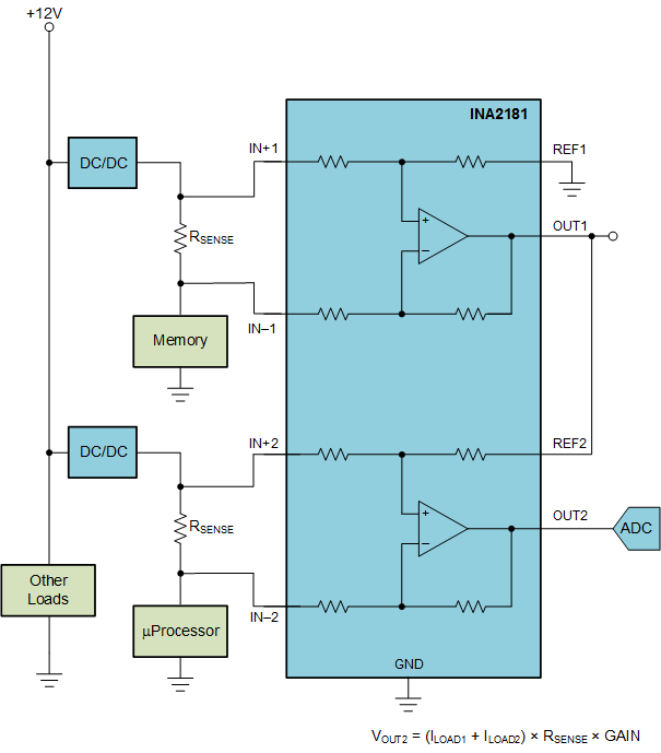
One approach would be to monitor both the CPU and memory current, multiplex the current to an ADC and then and add the resulting values together in a microprocessor. This approach requires some mathematical processing as well as an ADC to continually sample outputs at a fast enough rate to be effective. A better approach would be to use the REF pin of the INA2181 to add the current drawn by the memory to the current drawn by the CPU. This can be done by connecting the output of channel 1 that monitors the memory current to the REF2 pin as shown in Figure 1-3.
 Figure 1-3 Analog
Current Summing With INA2181
Figure 1-3 Analog
Current Summing With INA2181The channel 2 output will be the amplified sum of the currents from the CPU and memory. The current from the memory and the current from the total can be monitored when desired by an ADC. However, since the channel 2 output is an analog signal, a comparator with an appropriately set reference can be used to interrupt the system when an over current condition occurs. For this circuit to function properly the values of the two sense resistors must be the same.
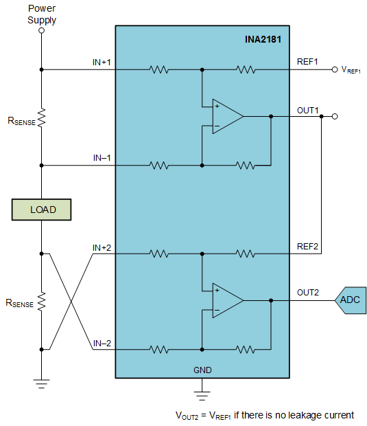
Another convenient use for multi-channel current monitors is to detect unexpected leakage paths. These leakage paths could be caused by unintended shorts to ground or some other potential not in the current measurement path. One technique to detect leakage current paths is to monitor all current going into and coming out of a circuit. As long as there are no unexpected leakage paths, the current into the load must equal the current coming out. To detect leakage currents all current in and out of a circuit should be monitored. If the currents in and out are equal, no unexpected current leakage path will be detected. Use of the dual current monitor provides a simple technique to detect leakage current paths without the need for multiple devices or the need to externally add or subtract currents. The circuit shown in Figure 1-4, uses the INA2181 to monitor the current into and out of a load.
By reversing the polarity of the resistor connections of the second amplifier and connecting the output of the first amplifier to the second amplifier, the current going in to the load is subtracted from the current going out.
 Figure 1-4 Current
Subtraction Using the INA2181, for Leakage Current Detection
Figure 1-4 Current
Subtraction Using the INA2181, for Leakage Current DetectionIf the voltage at OUT2 is equal to the applied reference voltage then no leakage path exists. If VOUT2 is higher than the applied reference voltage then there is unexpected current leaving the load. Likewise if VOUT2 is below the reference voltage then unexpected leakage current is entering the load. As before, for this circuit to function properly the values of the current sense resistors must be the same.
Texas Instruments offers several solutions for multichannel current monitoring. To monitor 4 channels the INA4180, INA4181, and INA4290 devices are available with an analog voltage output. The INA3221 provides the ability to accurately measure both system current and bus voltages for up to 3 independent channels. The values of the currents and voltages are reported through an I2C interface.
| DEVICE | OPTIMIZED PARAMETERS | PERFORMANCE TRADE-OFF |
|---|---|---|
| INA4180 | 4-channel analog current monitor | Unidirectional Measurement |
| INA4181 | Bidirectional 4-channel current monitor | Larger package |
| INA3221 | 3-channel digital current/voltage monitor | No analog output |
| 2-channel, 120-V analog current monitor | Unidirectional Measurement | |
| 4-channel, 120-V analog current monitor | Unidirectional Measurement |