TIDT205 February 2021
1 Description
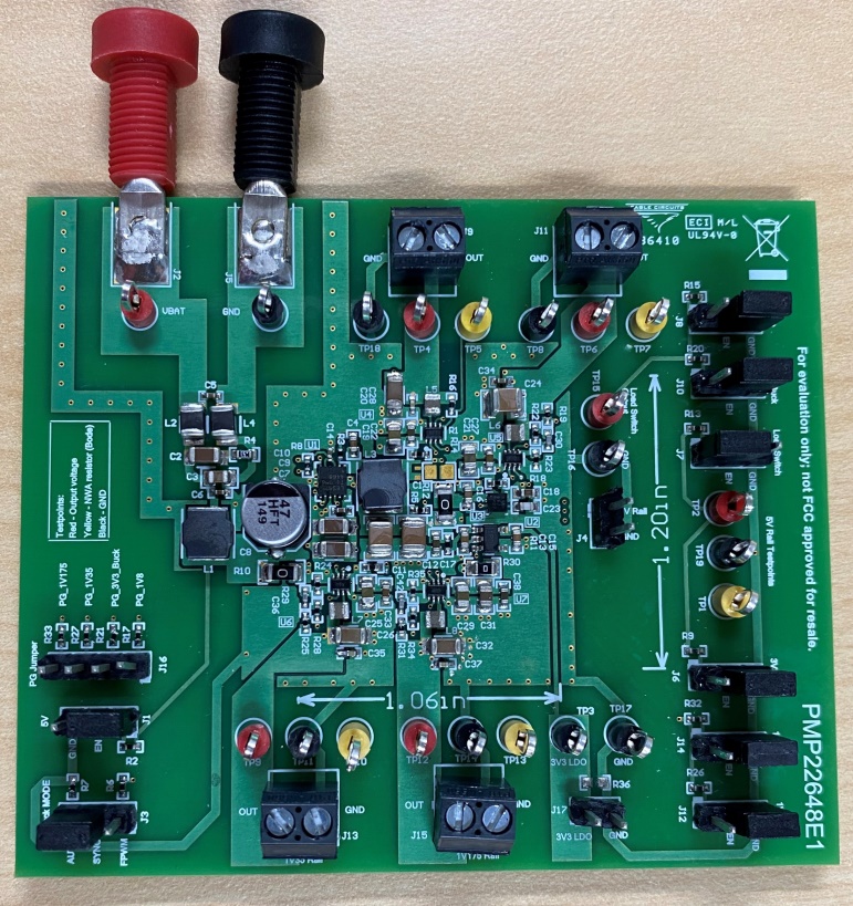
This reference design provides the system rails for automotive vehicle-to-everything power. A 5-V bus is generated by the off-battery buck converter (LM63625-Q1), and this supplies all the point-of-load devices. The bus converter switches at 2.1 MHz, and the load converters (TPS628501-Q1) switch at 2.2 MHz. Easily-configurable jumpers allow users to enable and disable each device on the board and toggle the bus converter operational modes. A front-end EMI filter is included.
 Figure 1-1 Board Top
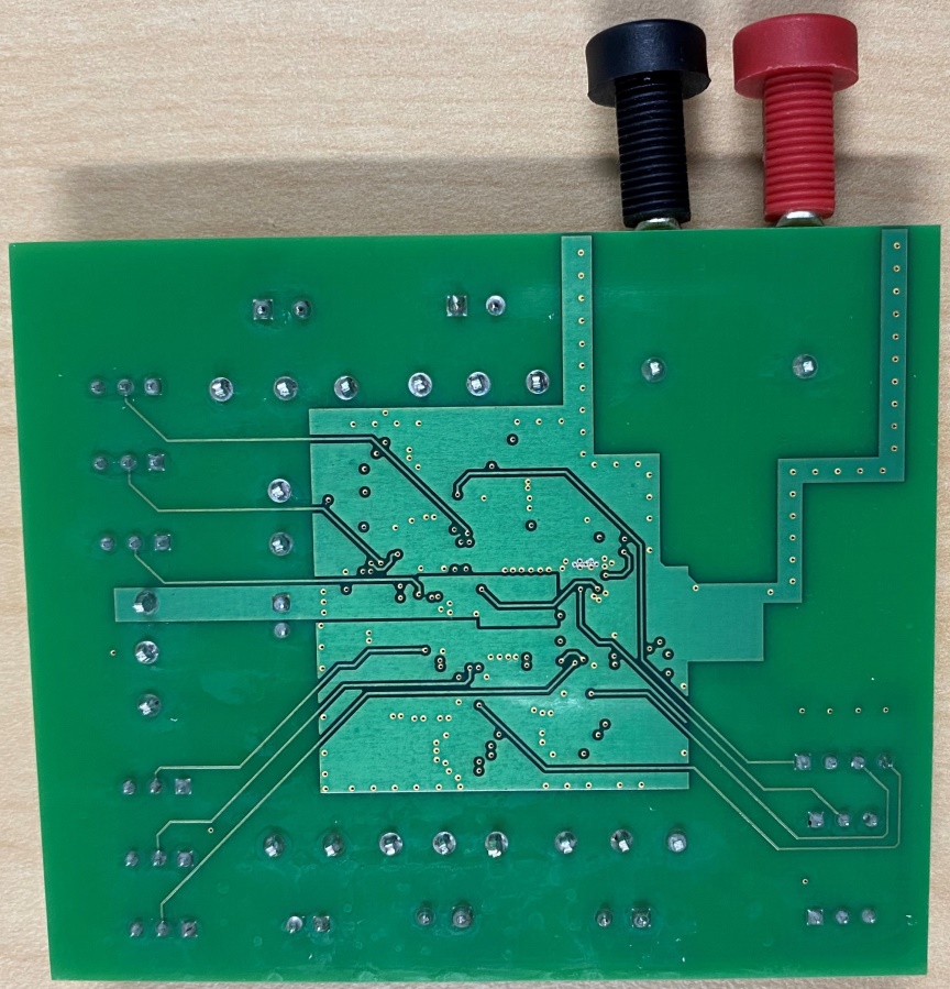
  Figure 1-2 Board Bottom