DLPU027D August 2014 – March 2019
7 EVM Setup
The DLP LightCrafter™ Display 2010 EVM is composed of three parts:
- Main board
- DLP LightCrafter Display board
- Engine with LED connection and Flex cable
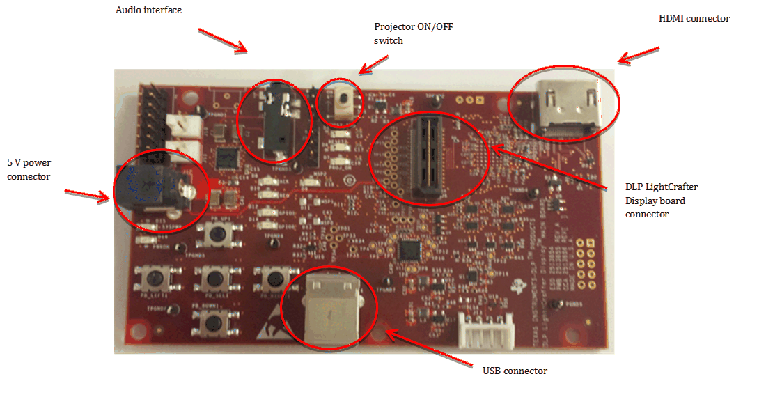
The main board contains the connector for the power supply, the USB connector to communicate to the DLP LightCrafter Display software, the HDMI, audio and the connector for the DLP LightCrafter Display board. The main board also contains the switch to turn on the projector in case the DLP LightCrafter Display board and the engine is connected. Figure 6 shows the main connectors on the main board.
 Figure 6. DLP LightCrafter Display main board
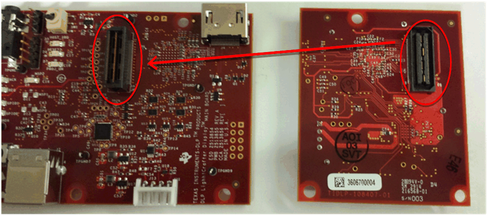
 The DLP LightCrafter Display board has three main connectors: the LED connector, the Flex cable connector, and the main board connector. To connect the main board to the DLP LightCrafter Display board, refer to Figure 7. Note that the main board connector on the DLP LightCrafter™ Display board is on the bottom while the LED and Flex cable connectors are on the top.
 Figure 7. Connection Main Board and DLP LightCrafter Display Board
 Figure 8 shows the board connections.
 Figure 8. DLP LightCrafter Display
 The engine requires four connections:
- two connections from the flex cable:
- one for the DMD
- one for the flash card mounted on the engine
- two connections from a small adapter board to ensure communication with the LEDs
Figure 9 shows the proper setup.
The pins of the flex cable connector are labeled with the pin numbers. Verify that the pin numbers match when connecting the flex cable.
To ensure the LED cables are connected correctly, use the colored circles to trace each cable to the right connection. Figure 9 shows how to verify the connection. .
 Figure 9. LED Connection and Flex Cable Connection
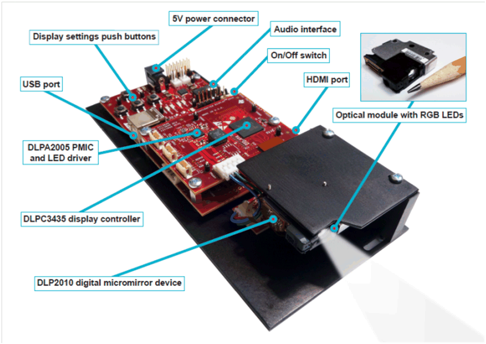
 Figure 10 shows the final setup of all components.
 Figure 10. DLP LightCrafter Display complete EVM
 Make sure that everything is setup correctly before continuing. Verify that the flex cable is connected correctly to the DMD and to the LightCrafter Display board.