SBAA275A June   2018  – March 2023 ADS1120 , ADS112C04 , ADS112U04 , ADS1147 , ADS1148 , ADS114S06 , ADS114S06B , ADS114S08 , ADS114S08B , ADS1220 , ADS122C04 , ADS122U04 , ADS1247 , ADS1248 , ADS124S06 , ADS124S08 , ADS125H02 , ADS1260 , ADS1261 , ADS1262 , ADS1263


  1.   A Basic Guide to RTD Measurements
  2. 1RTD Overview
    1. 1.1 Callendar-Van Dusen Equation
    2. 1.2 RTD Tolerance Standards
    3. 1.3 RTD Wiring Configurations
    4. 1.4 Ratiometric Measurements
      1. 1.4.1 Lead Resistance Cancellation
      2. 1.4.2 IDAC Current Chopping
    5. 1.5 Design Considerations
      1. 1.5.1 Identify the RTD Range of Operation
      2. 1.5.2 Set the Excitation Current Sources and Consider RTD Self Heating
      3. 1.5.3 Set Reference Voltage and PGA Gain
      4. 1.5.4 Verify the Design Fits the Device Range of Operation
      5. 1.5.5 Design Iteration
  3. 2RTD Measurement Circuits
    1. 2.1  Two-Wire RTD Measurement With Low-Side Reference
      1. 2.1.1 Schematic
      2. 2.1.2 Pros and Cons
      3. 2.1.3 Design Notes
      4. 2.1.4 Measurement Conversion
      5. 2.1.5 Generic Register Settings
    2. 2.2  Two-Wire RTD Measurement With High-Side Reference
      1. 2.2.1 Schematic
      2. 2.2.2 Pros and Cons
      3. 2.2.3 Design Notes
      4. 2.2.4 Measurement Conversion
      5. 2.2.5 Generic Register Settings
    3. 2.3  Three-Wire RTD Measurement, Low-Side Reference
      1. 2.3.1 Schematic
      2. 2.3.2 Pros and Cons
      3. 2.3.3 Design Notes
      4. 2.3.4 Measurement Conversion
      5. 2.3.5 Generic Register Settings
      6. 2.3.6 Chopping IDAC Currents for Matching
    4. 2.4  Three-Wire RTD Measurement, Low-Side Reference, One IDAC Current Source
      1. 2.4.1 Schematic
      2. 2.4.2 Pros and Cons
      3. 2.4.3 Design Notes
      4. 2.4.4 Measurement Conversion
      5. 2.4.5 Configuration Register Settings
    5. 2.5  Three-Wire RTD Measurement, High-Side Reference
      1. 2.5.1 Schematic
      2. 2.5.2 Pros and Cons
      3. 2.5.3 Design Notes
      4. 2.5.4 Measurement Conversion
      5. 2.5.5 Configuration Register Settings
    6. 2.6  Four-Wire RTD Measurement, Low-Side Reference
      1. 2.6.1 Schematic
      2. 2.6.2 Pros and Cons
      3. 2.6.3 Design Notes
      4. 2.6.4 Measurement Conversion
      5. 2.6.5 Configuration Register Settings
    7. 2.7  Two Series Two-Wire RTD Measurements, Low-Side Reference
      1. 2.7.1 Schematic
      2. 2.7.2 Pros and Cons
      3. 2.7.3 Design Notes
      4. 2.7.4 Measurement Conversion
      5. 2.7.5 Configuration Register Settings
    8. 2.8  Two Series Four-Wire RTD Measurements
      1. 2.8.1 Schematic
      2. 2.8.2 Pros and Cons
      3. 2.8.3 Design Notes
      4. 2.8.4 Measurement Conversion
      5. 2.8.5 Configuration Measurement Settings
    9. 2.9  Multiple Two-Wire RTD Measurements
      1. 2.9.1 Schematic
      2. 2.9.2 Pros and Cons
      3. 2.9.3 Design Notes
      4. 2.9.4 Measurement Conversion
      5. 2.9.5 Configuration Register Settings
    10. 2.10 Multiple Three-Wire RTD Measurements
      1. 2.10.1 Schematic
      2. 2.10.2 Pros and Cons
      3. 2.10.3 Design Notes
      4. 2.10.4 Measurement Conversion
      5. 2.10.5 Configuration Register Settings
    11. 2.11 Multiple Four-Wire RTD Measurements in Parallel
      1. 2.11.1 Schematic
      2. 2.11.2 Pros and Cons
      3. 2.11.3 Design Notes
      4. 2.11.4 Measurement Conversion
      5. 2.11.5 Configuration Register Settings
    12. 2.12 Universal RTD Measurement Interface With Low-Side Reference
      1. 2.12.1 Schematic
      2. 2.12.2 Pros and Cons
      3. 2.12.3 Design Notes
        1. 2.12.3.1 Universal Measurement Interface - Two-Wire RTD
        2. 2.12.3.2 Universal Measurement Interface - Three-Wire RTD
        3. 2.12.3.3 Universal Measurement Interface - Four-Wire RTD
      4. 2.12.4 Measurement Conversion
        1. 2.12.4.1 Two-Wire Measurement
        2. 2.12.4.2 Three-Wire Measurement
        3. 2.12.4.3 Four-Wire Measurement
      5. 2.12.5 Configuration Register Settings
    13. 2.13 Universal RTD Measurement Interface With High-Side Reference
      1. 2.13.1 Schematic
      2. 2.13.2 Pros and Cons
      3. 2.13.3 Design Notes
        1. 2.13.3.1 Universal Measurement Interface, High-Side Reference - Two-Wire RTD
        2. 2.13.3.2 Universal Measurement Interface, High-Side Reference - Three-Wire RTD
        3. 2.13.3.3 Universal Measurement Interface, High-Side Reference - Four-Wire RTD
      4. 2.13.4 Measurement Conversion
        1. 2.13.4.1 Two-Wire Measurement
        2. 2.13.4.2 Three-Wire Measurement
        3. 2.13.4.3 Four-Wire Measurement
      5. 2.13.5 Configuration Register Settings
  4. 3Summary
  5. 4Revision History

Lead Resistance Cancellation

In Figure 1-5, the lead resistances of a three-wire RTD are shown and a second excitation current source is added, labeled IDAC2.
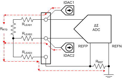
GUID-C83FFC0E-BBA1-42FC-BF06-1C588100646B-low.gifFigure 1-5 Example of Lead Wire Resistance Cancellation

With a single excitation current source, RLEAD1 adds an error to the measurement. By adding IDAC2, the second excitation current source is used to cancel out the error in the lead wire resistance. When adding the lead resistances and the second current source, the equation becomes:

Equation 6. Output code = 223 • [IIDAC1 • (RRTD + RLEAD1) – (IIDAC2 • RLEAD2)] / [(IIDAC1 + IIDAC2) • RREF]

If the lead resistances match and the excitation currents match, then RLEAD1 = RLEAD2 and IIDAC1 = IIDAC2. The lead wire resistances cancel out so that Equation 6 reduces to the result in Equation 7 maintaining a ratiometric measurement.

Equation 7. Output code = 223 • RRTD / (2 • RREF) = 222 • RRTD/ RREF
Equation 8. RRTD = Output code • RREF / 222

RLEAD3 is not part of the measurement, because it is not in the input measurement path or in the reference input path.