SBAA530 September 2021 TMAG5170 , TMAG5170-Q1 , TMAG5173-Q1
1 Achieving High Accuracy at High Speeds
Achieving the highest accuracy possible often requires running a system at a lower speed, which decreases system performance. For applications requiring fast, real-time control – highly accurate measurements at high speeds – decreased system performance is not an option. One application with these requirements is a motor transport system, also known as a linear mover. A linear mover consists of a smart track system with built-in microcontrollers (MCUs) that enable independent positioning of each mover. This system configuration provides multiple advantages in automation control, including high transfer speeds, accurate positioning and the ability to move products forward and backward on the line to increase manufacturing efficiency.
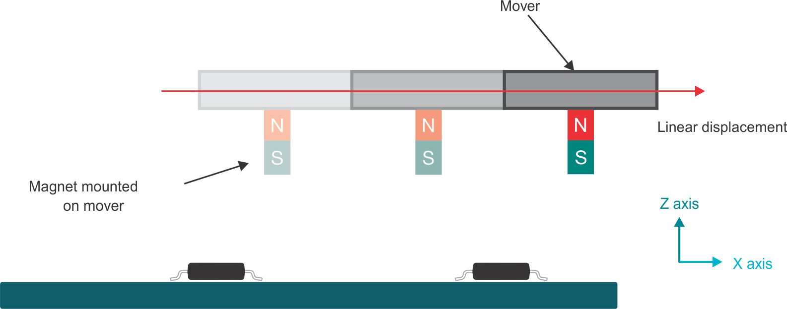
Linear movers use an array of sensors to track the absolute position of a magnet mounted on the mover. As Figure 1-1 shows, the sensors are placed equidistant along the X-axis. Calculating the angle from the X and Z components of the magnetic fields using the adjacent linear 3D Hall-effect position sensors resolves the absolute position of the mover.

Figure 1-1 Conceptual Implementation of a Linear Mover Using Two Linear 3D Hall-Effect Position Sensors
For linear mover systems that require accuracy and high speeds, a high-performance linear 3D Hall-effect position sensor can reduce errors. Internally, these error sources occur because of sensitivity, offset, linearity, noise produced by temperature variations and input-referred magnetic noise that couples into each axis. Externally induced errors come from many sources: mechanical vibration, unintentional spatial variations and tolerances between the magnet and the sensor, fast-changing magnetic fields, and off-axis angle measurements.
An important aspect of a high-performance linear 3D Hall-effect position sensor is an onboard angle coordinate rotation digital computer (CORDIC) calculator that performs iterative trigonometric approximations in a two-dimensional space to calculate both angle and magnitude, achieving a resolution of 0.25 degrees. Performing this calculation on the device eliminates the need to post-process the magnetic information.
Fast-changing magnetic fields are problematic for linear 3D Hall-effect position sensors that do not have independent internal signal paths, which include single-axis measurement, gain adjustment, filtering, and data conversion. To reduce errors, 3D Hall-effect position sensors with a single data converter and a feature called pseudo-simultaneous sampling provide the best solution.
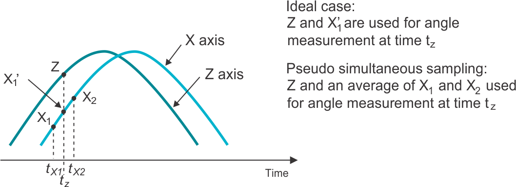
Figure 1-2 illustrates the ideal circumstance where sampling of Z and X1’ occurs at the same instance in time. With changing magnetic fields and a single signal path for taking measurements; however, this is not possible. With pseudo-simultaneous sampling, an average of the X component just before and just after X1‘ (labeled X1 and X2, respectively) is used as the X-axis value that matches up to Z. Assuming that changes in the B-fields are relatively linear over small intervals, the results are similar to the sampling of both axes at the same time.

Figure 1-2 XZX Pattern Example of Pseudo-Simultaneous Sampling
Linear 3D Hall-effect position sensors typically house sensor technologies that enable the sensing of magnetic fields both in-plane and perpendicular to the package. Because these are two distinct sensors, the magnetic noise for each is different. Therefore, it is advantageous to equalize the noise floor by averaging samples of each axis. A linear 3D Hall-effect position sensor that can average as many as 32 samples reduces the noise floor substantially.
A high-accuracy 3D Hall-effect position sensor that can take precise measurements at high speeds – such as the TMAG5170 – is very useful for this application. The TMAG5170 delivers ultra-high accuracy thanks to a maximum full-scale sensitivity error of ±2.6%, low sensitivity mismatch error (per axis), and low drift overtemperature. Such precision could eliminate the need for system-level calibration, which decreases total system cost. Additionally, the TMAG5170 delivers sample rates as high as 20 kSPS, which is fast enough for many linear mover applications. For more information on the impact of sample rate, see the Angle Measurement with Multi-Axis Hall-Effect Sensors application report.