SBAA545 August 2022 DRV5013 , DRV5013-Q1 , TMAG5110 , TMAG5110-Q1 , TMAG5111 , TMAG5111-Q1
1 Introduction
While formerly considered a luxury, motor-driven windows, sunroofs, seats, and other accessories are common-place in modern vehicles. Some applications - like a window regulator - need only a single motor module to support movement through a single dimension. Other applications, like an adjustable seat can require three or more distinct modules to support movement in multiple planes.
At a high level, automotive body modules are composed of a tri-state human machine interface (HMI) switch that translates user-mechanical input into an electrical stimulus that is then processed by a microcontroller that initiates a bridge circuit to spin a motor. The spinning motor connects to a gear box that trades speed for torque to move the window. Depending on whether the window is engaged by the driver or the passenger, window movement can be transitory and occur while the tri-state switch is engaged. Or a transitory press is sufficient to make the window completely open or closed. Such behavior as the latter, requires yet another circuit block of feedback.
Figure 1-1 illustrates a high-level view of the intended system operation. Section 2 and Section 3 provide some insight on the electromechanical chain between the motor and window and the Hall-effect feedback system that controls the window.
A motor-driven accessory, like a power window, uses a lever or belt-driven actuator driven by a motor module which in turn contains a motor, gear train, external electrical connections, and mechanical couplings, all integrated into a rugged housing. The example in this application note focuses on a window regulator that uses a geared lever in a scissor-arm assembly to move a window glass pane vertically, as shown in Figure 1-2.
The most common motor choice is a low-cost, brushed DC motor which, unlike brushless motors, has no built-in sensors. As a result, some kind of external monitoring is needed for estimating the position, speed, and direction of a motor. For example, monitoring the window position informs the system if a window is 25%, 50%, or 100% closed. Monitoring the window can also allow the control system to balance a desired open or close speed requirement with motor efficiency. In either case, estimating window position, speed, and direction is best accomplished by directly monitoring the motor rotation and direction.
One way to estimate motor position, direction, and speed is to monitor the motor supply voltage, current, or both, and then count ripple axis crossings that occur as the motor revolves. While seeming like a useful approach, this method bases the estimates on an indirect metric – power supply ripple – and does not directly monitor the actual turning of the motor, and the physical movement of the accessory. Excess ripple caused by poor electrical connections, aging components, or EMI can result in unreliable estimates of direction, speed, and position.
An efficient and accurate method to directly monitor the turning motor is by mounting a multipole ring magnet on the motor shaft and using Hall-effect sensors and latches to monitor the magnetic field variations as the shaft spins, as illustrated in Figure 1-3. While this approach uses a magnet, the method has the advantage of directly monitoring the turning motor shaft and providing accurate estimates of motor position, speed, and direction.
Figure 1-4 shows a more detailed view of the motor-monitoring devices and the early stage of the regulator gear train. The multipole ring magnet on the turning motor shaft is monitored by Hall-effect sensors mounted on a nearby PC board. As the spinning ring magnet moves through successive changes in north and south polarity, the Hall sensors provide output signals based on the time-varying magnetic fields.
The Hall sensors recommended for this application are latches, with output behavior illustrated in Figure 1-5. These devices have high or low binary outputs that are functions of the detected field relative to the internal threshold of that device. These thresholds are typically symmetric about zero (0 mT) with the BOP trigger corresponding to a positive, magnetic-south field passing through the Hall-element of the device and the BRP trigger corresponding to a positive, magnetic-north field passing through the Hall-element of the device.
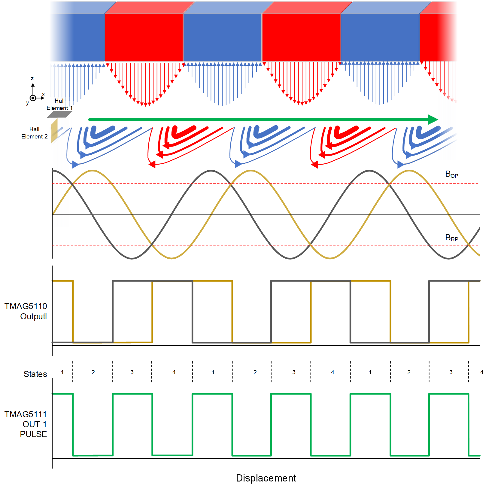
Figure 1-6 illustrates how the alternating polarity of the magnetic field causes the output of the Hall sensor to change as the motor shaft rotates. Each polarity flip of the magnetic field causes an output state change for a Hall element and every two polarity flips results in a pulse on the output of a single Hall-element latch. Considering a device with orthogonal Hall elements, it is possible with additional logic circuitry to get an output pulse every time a pole moves past the Hall sensor. A rotating motor shaft and magnet results in a train of pulses that can be monitored and counted by a microcontroller for customized feedback control. For more details, see the TMAG511x 2D Latch Benefits application note.
 Figure 1-6 TMAG5111 Operation
The goal of this application note is to examine the impact of the mechanical assemblies - levers, gears, and so forth - on the choices for the magnet and Hall sensors, which are in turn used to track position, speed, and direction of the window, sunroof, or seat. The remainder of this document is divided into several sections. Section 2 provides a high-level description of a lever-based window regulator as well as some basic parameters used in the example developed in this paper. Section 2.2 provides a description of the mechanical parts (levers, gears, and so forth) of the window regulator that serve as part of the electromechanical signal chain. Section 3 gives an overview of Hall-effect latches and their parameters that most readily impact this application. The Analysis and Results section provides simulation results of the magnet and Hall sensors that reflect the underlying requirements and gives some recommendations for design and selection of the magnet and Hall device.