SBAA577 March 2023 TMAG5170 , TMAG5273
5 Analysis of Error Sources
- Error in installation position
and direction error of Hall sensor board. For example, the Hall sensor is not
directly under magnet and its axis does not coincidence with the bumper’s
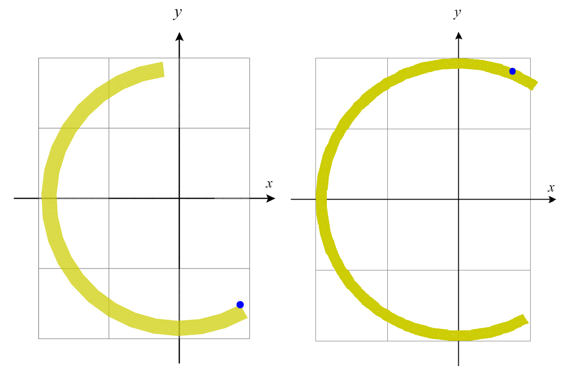
central axis. The installation error can cause the magnets movement trace to
behave as shown in Figure 5-1. In this instance the measured angle should have been 0° through
approximately180° but due to the shift the result was 5° through approximately
195° and a bigger shift could result in -15° through approximately 195°.
 Figure 5-1 Magnet Position Trace
Due to Installation Error
 - The bottom of the magnet is not
parallel to Hall sensors package. This slight offset will also generate an angle
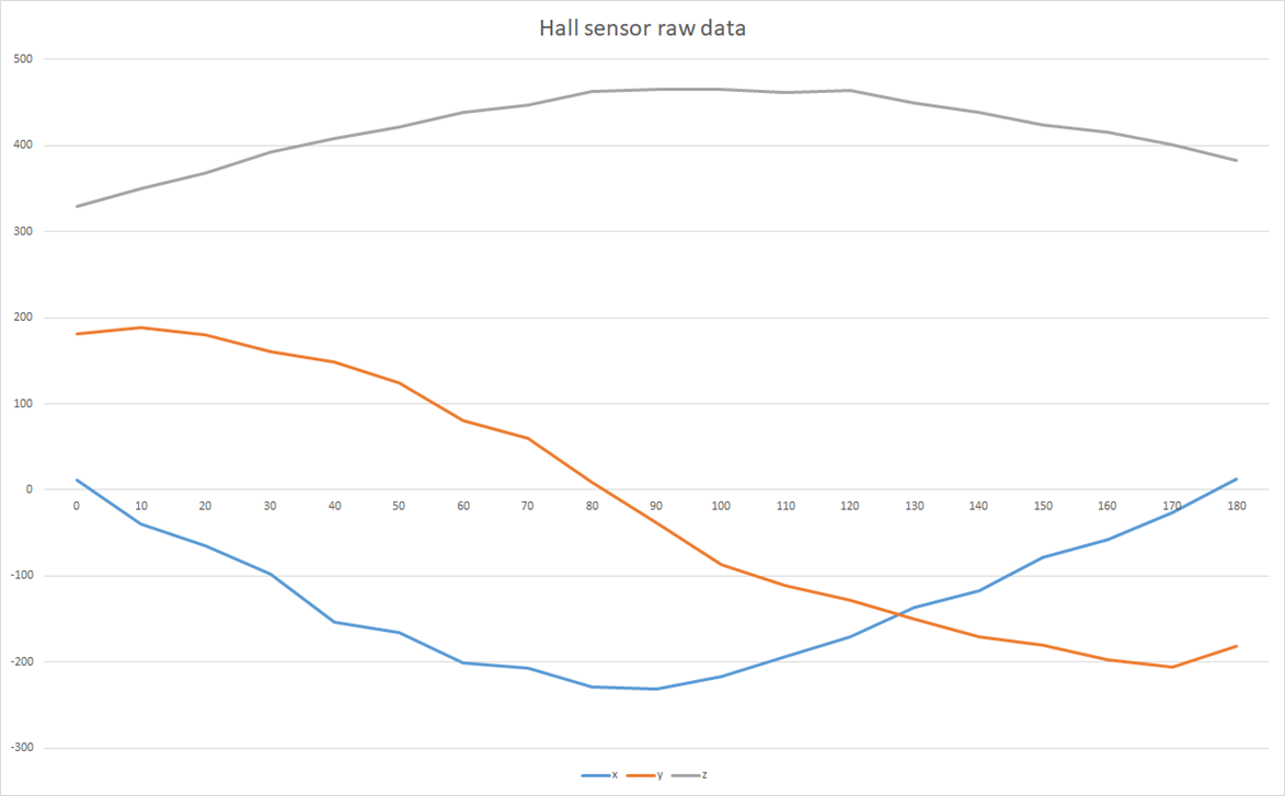
between the magnet and the sensor IC generating an error as seen in Figure 5-1. This shift magnet can also cause the waveform of output data to no be as
smooth and symmetrical like the data shown in Figure 4-3. Figure 5-2 shows measured data when the magnet is not parallel to the Hall sensor.
 Figure 5-2 Hall Sensor Output Raw
Data From 0° Through Approximately 180° of Collision
 - Low SNR, the sensors SNR depends on the distance between magnet and sensor, the magnets strength, and the Hall sensors range setting. The TMAG5170 offers two different sensitivities each with three configurable range settings. These options range from ±25 to ±300 mT.
- Uneven lateral deformation of spring.
- Impact of robot movement speed,
direction and spring strength and surface material.
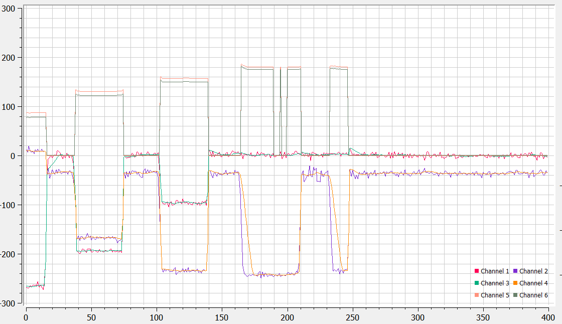
 Figure 5-3 Raw and Filtered Data
Wave of Hall Sensor
For most general mechanical errors in mass production, after using statistical curve-fit calculation of full-scale data. The measurement error can be reduced in the R&D designing phase to ensure accuracy needed by the system. A second order curve-fit equation mostly reduces error and helps meet error requirements. Source data of equation should be raw angle data of X and Y axis, instead of using raw magnetic data of the X and Y axis. The raw arctangent angle should be calculated first because collision depth will be related to curve-fit angle if directly using raw X and Y magnetic data.
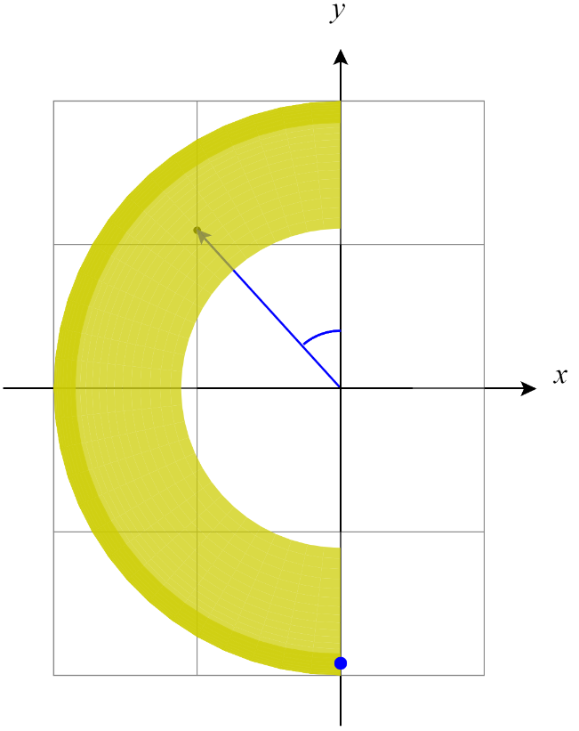
 Figure 5-4 Magnet Position Trace After
Adding Threshold
Figure 5-4 Magnet Position Trace After
Adding ThresholdSetting a data threshold to set a calculation point. This helps by filtering noise generated by the moving robot. The magnet point trace after collision is shown on Figure 5-4.
The error caused by robot moving can be mainly attributed to the robots’ speed, moving direction, spring strength, and material of bumper surface. Due to the impact’s direction, since it is not toward the central portion of the bumper arc, this collision can cause a relatively large error between measuring angle and real collision angle when using the Hall sensor output data. As shown in Figure 5-5, an equation can help by compensating for the robot speed and direction raw angle data.
 Figure 5-5 Collision Force When Robot
Moving