SBOU209B August 2019 – August 2021 TMCS1100 , TMCS1100-Q1
4 Operation
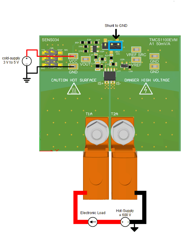
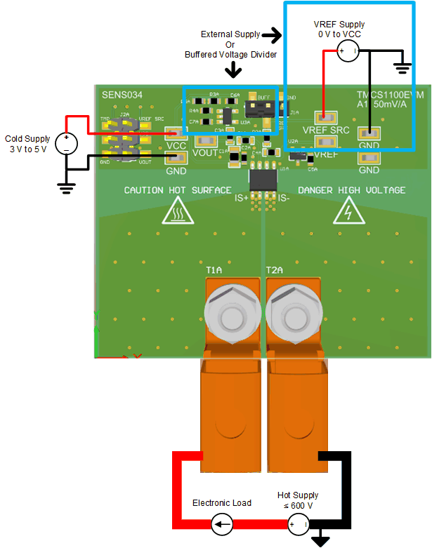
The following are instructions to set up and use the TMCS1100EVM. For the following instructions, x = A to D for the A1 to A4 gain variants, respectively. Figure 4-1 shows an example of a simple, low-side, unidirectional setup on the A1 (50 mV/A) gain variant (x = A). For bidirectional measurements, the user can either connect jumper J1x to the buffer with a custom voltage divider set by the user, or connect an additional external supply to the VREF SOURCE and GND test points, as shown in Figure 4-2. This device has isolation; external supplies are distinguished by hot for load, cold for DUT supply, and REF for VREF supply. Short the GND terminals for the cold and REF supplies together. The hot supply can be isolated and at a different potential.
 Figure 4-1 Low-Side Unidirectional Setup
 Figure 4-2 Low-Side Bidirectional Setup
- For greater maneuverable flexibility, break apart the EVM sub boards along the score lines. Otherwise, the board can be left intact.
- Attach the high-current lug connectors to IS+ and IS– of the gain version to be tested.
- Connect the terminals of an external cold supply to the GND and VCC test points on the EVM gain variant of choice. Be sure to connect GND first and make sure that the external cold supply is between 3 V and 5.5 V.
- To set the VREF voltage, use an external REF supply, use a buffered voltage divider, or short VREF to GND. When VREF is supplied by the buffered voltage divider, set the jumper to short VREF to the buffer pin on connector J1x. When the VREF voltage is supplied by an external REF supply, remove the jumper short from J1x, and apply a supply to the VREF SOURCE and GND test points with a voltage set between GND and VCC.
- Connect the input per Section 4.1.
Do not leave EVM powered when unattended.
Hot surface. Contact may cause burns. Do not touch!