SCLA017A July   2019  – April 2021 SN74HC595


  1.   Trademarks
  2. 1Block Diagram
  3. 2Optimizing System Controller I/O Usage
  4. 3Logic and Translation Use Cases
    1. 3.1 Logic Use Cases
      1. 3.1.1 Combine Power Good Signals
      2. 3.1.2 Debounce Switches and Buttons
      3. 3.1.3 Increase Number of Controller Inputs
      4. 3.1.4 Increase Number of Controller Outputs
    2. 3.2 Voltage Translation Use Cases
      1. 3.2.1 SPI Communication
      2. 3.2.2 RMII Communication
  5. 4Recommended Logic and Translation Families for Network Switches
    1. 4.1 AXC: Advanced eXtremely Low-Voltage CMOS Translation
    2. 4.2 LVC: Low-Voltage CMOS Logic and Translation
    3. 4.3 HC: High-speed CMOS Logic
  6. 5Revision History

Block Diagram

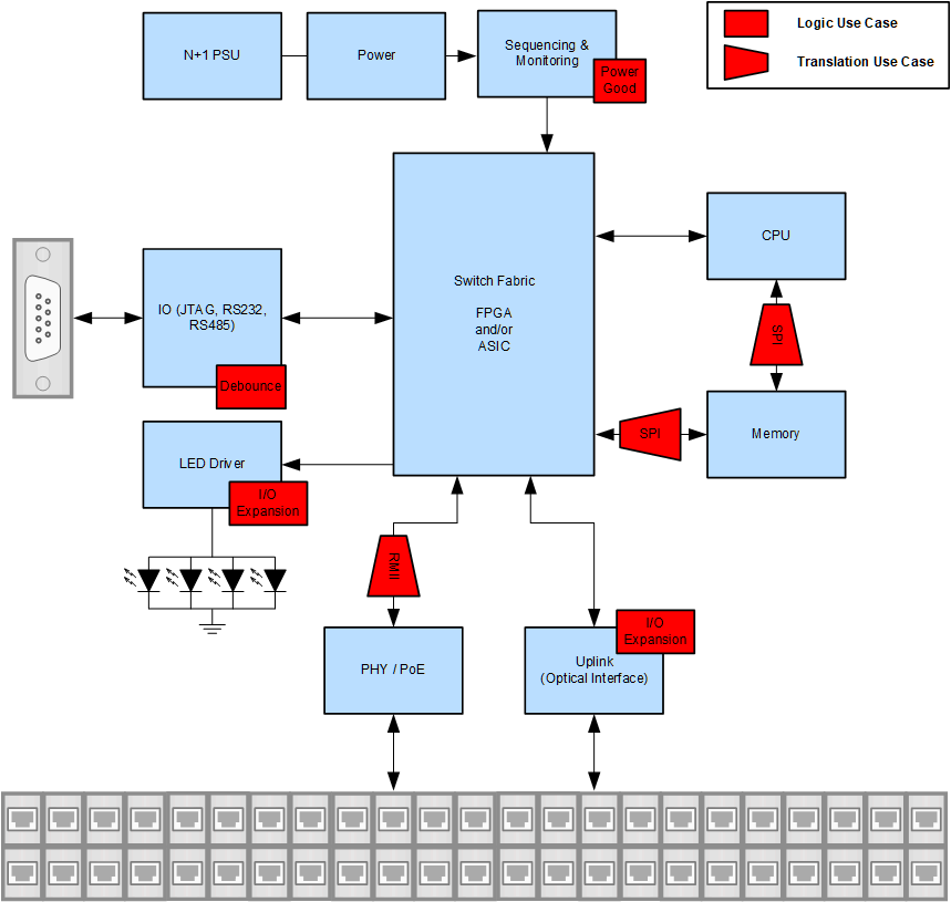
GUID-6C7ED3FD-9DC4-44D9-8FF9-5A9024A52BF8-low.gifFigure 1-1 Simplified Block Diagram for Campus and Branch Switches

There are two primary types of Network switches, Campus and Branch as well as Data Center switches. Both of these types of switches have similar design architecture so the highlighted use cases apply to both. A simplified Campus and Branch system block diagram is used to illustrate the logic and translation use cases for the purpose of this report. See the interactive online End Equipment Reference Diagram Campus and Branch switches and Data Center switches for a more complete view.