SLAA907D September 2019 – December 2021 PGA450-Q1 , PGA460 , PGA460-Q1 , TDC1000 , TDC1000-Q1 , TDC1011 , TDC1011-Q1 , TUSS4440 , TUSS4470
3.2 Acoustic Impedance
Sound waves can travel through various types of medium to detect objects with significant acoustic impedance mismatch. Acoustic impedance (Z) is defined as a product of density and acoustic velocity. Air has much lower acoustic impedance compared to most liquids or solids.
| Material | Density
Equation 2.  | Acoustic Velocity
Equation 3.  | Acoustic Impedance
Equation 4.  |
|---|---|---|---|
| Air | 1.3 | 330 | .00429 |
| Water | 1000 | 1450 | 1.45 |
| Muscle | 1075 | 1590 | 1.70 |
| Aluminum | 2700 | 6320 | 17.1 |
| Iron | 7700 | 5900 | 45.43 |
| Steel | 7800 | 5900 | 46.02 |
| Gold | 19320 | 3240 | 62.6 |
| Skin | 1109 | 1540 | 1.6 |
The difference in acoustic impedance (Z) between two objects is defined as impedance mismatch (see Equation 5). The greater the impedance mismatch, the greater percentage of energy is reflected at the boundary between the two mediums.

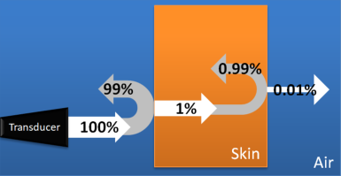
Example 1: Air and skin:
 Figure 3-2 Reflection Coefficients for
Skin and Air Boundaries
Figure 3-2 Reflection Coefficients for
Skin and Air BoundariesThe acoustic impedance of air is .00429 and the acoustic impedance of skin is 1.6. Putting these values in the reflection coefficient yields Equation 6:

Performing this calculation at every boundary dictates how much energy is reflected back, how much is absorbed within the material, and how much is permeated through.
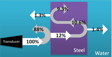
Example 2: Water and steel:
 Figure 3-3 Reflection Coefficients for
Water and Steel Boundaries
Figure 3-3 Reflection Coefficients for
Water and Steel BoundariesSimilarly, for liquid-based detection, a water and steel boundary reflects back 88% of the transmitted echo using the same equation (Equation 6).