SLAA908A September 2019 – September 2021 MSP430FR2032 , MSP430FR2032 , MSP430FR2033 , MSP430FR2033 , MSP430FR2153 , MSP430FR2153 , MSP430FR2155 , MSP430FR2155 , MSP430FR2310 , MSP430FR2310 , MSP430FR2311 , MSP430FR2311 , MSP430FR2353 , MSP430FR2353 , MSP430FR2355 , MSP430FR2355 , MSP430FR2422 , MSP430FR2422 , MSP430FR2433 , MSP430FR2433 , MSP430FR2475 , MSP430FR2475 , MSP430FR2476 , MSP430FR2476 , MSP430FR4131 , MSP430FR4131 , MSP430FR4132 , MSP430FR4132
3.2 Read N Bytes From Slave Device
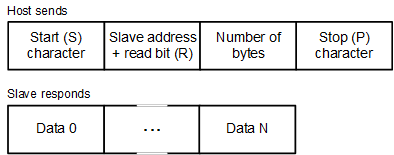
The host issues the read command by sending an S character followed by an I2C bus slave device address, and the total number of bytes to be read from the addressed I2C bus slave. The frame is then terminated with a P character. Once the host issues this command, the MSP430 MCU will access the I2C bus slave device, get the correct number of bytes from the addressed I2C bus slave, and then return the data to the host.
The second byte sent is the I2C bus device slave address. The least significant bit (R) of this byte must be set to 1 to indicate this is an I2C bus write command.
 Figure 3-2 Read N Bytes From Slave Device