SLAA976 October 2020 MSP430FR5041 , MSP430FR5043 , MSP430FR6005 , MSP430FR6007 , MSP430FR6041 , MSP430FR6043 , MSP430FR6045 , MSP430FR6047
4 Extracting O2 Concentration
Table 4-1 Spreadsheet Example
| A | B | C | D | E | F | |
|---|---|---|---|---|---|---|
| 1 | Absolute TOF UPS (μs) | Absolute TOF DNS (μs) | Velocigty of Gas Flow (m/s) | Speed of Sound in Gas Medium (m/s) | Oxygen Concentration (%) | Calibration Parameter |
| 2 | 132.9382 | 132.9738 | -0.04426 | 330.936511 | 21.04397223 | 14.6 |
- Use TOF values to calculate velocity
of gas flow.
- For cell C2 “=(0.044/2)*(1/(B2*0.000001) - 1/(A2*0.000001))” – Using Equation 2.
- Use TOF values to Calculate speed of
sound in gas medium.
- For cell D2
“=(0.044/(B2*0.000001) - C2)”
- Solving for C in (1) -> C = (L / T12) - V
- For cell D2
“=(0.044/(B2*0.000001) - C2)”
- Calculate Oxygen concentration.
- For cell E2 “=100*((1.4*8.314*295.85/(D2+F2)^2)-(28/1000))/(4/1000)” – Using Equation 4.
- Calibrate measurements.
- Since the oxygen concentration in this measurement is known to be 21% (Air), change the value of cell F2 until Cell E2 equals 21%. In this case, many sample points were taken with air and averaged.
- The calibration parameter “14.6” can now be applied to the whole data set.
- This calibration parameter is unique to this specific set-up. A calibration procedure must always be performed for any new implementation.
- Applying calibrated equation to dataset.
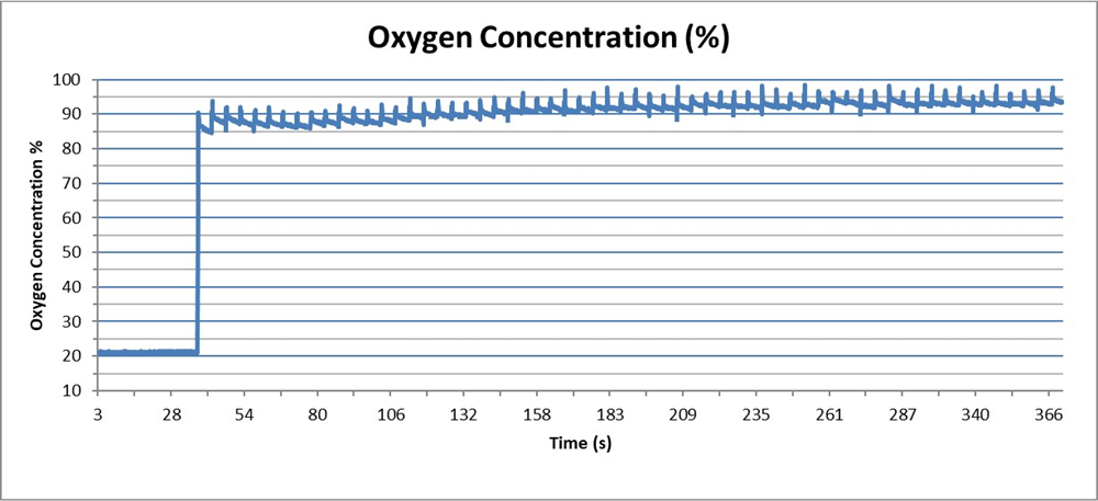
 Figure 4-1 Oxygen Concentration
Extraction
Figure 4-1 Oxygen Concentration
ExtractionAs it can be seen in Figure 4-1, the oxygen concentration ramps up from 21% to 93.4%. Based on the manufacturer’s certification report for the specific unit used, our system was 0.8% off from the specified oxygen concentration. This was all achieved using air as a single calibration point and could easily be implemented with the MSP430FR6043.
Table 4-2 Performance and Comparison
| Parameter | Zirconium Sensor | Competing USS Solution | TI’s USS |
|---|---|---|---|
| Measurement Range | 0.1% - 100% | 0% – 100% | 0% - 100% |
| Accuracy | ± 3% - 0.5% FS | ±3 - 1.8% FS | ± 1.7% – 0.5% RD |
| Power Consumption | 1 – 10W | 0.6W | 660 µW @10SPS |
| Warm up time | ~60s | NA | NA |
| Response time | 4s – 30s | 0.5s | 78ms |
| Output Stabilization time | 2 – 10 minutes | NA | NA |
| Lifetime | 1-3 years | > 5 Years | > 5 Years |