SLAAE57 June 2022 TAS2563
1.1 PDM Microphone Hardware Connections
Besides the power supply, the PDM microphone usually needs two signals to work. The two signals are PDM CLK and PDM data. The PDM data can be available at the rising edge or falling edge of PDM CLK. Obtain this data from the PDM Timing Diagram (illustrated in Figure 1-2) in the TAS2563 6.1-W Boosted Class-D Audio Amplifier With Integrated DSP and IV Sense data sheet.
 Figure 1-2 PDM Timing Diagram
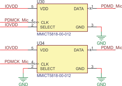
The two PDM microphones can be connected together. One PDM microphone works at the CLK raising edge and the other one works at the CLK failing edge. The chipset reads the data both at the raising edge and failing edge but splits them. So, the chipset gets signals of the two PDM microphones.
For example, the PDM microphone has 5 pins, shown in Table 1-1. The SELECT pin can be set high or low to determine which signal edge makes the microphone data available.
| Pin # | Pin Name | Type | Description |
|---|---|---|---|
| 1 | DATA | Digital O | PDM Output |
| 2 | SELECT | Digital I |
Lo/Hi (L/R) Select Connect to VDD or GND |
| 3 | GROUND | Power | Ground |
|
4 |
CLOCK | Digital I | Clock Input |
|
5 |
VDD | Power | Power Supply |
On the TAS2X63EVM, the two microphones are connected together, but the select pins are set to low or high in different levels. The two microphones work independently in the system.
 Figure 1-3 PDM Hardware Connections