SLAAE63 August 2022 MSP430FR2353 , MSP430FR2353 , MSP430FR2355 , MSP430FR2355
4 Bench Test Performance
Lab tests were performed using the MSP430FR2355 LaunchPad™ development kit. The program was developed with Code Composer Studio™ IDE (Version 12.0.0), and the code size is approximately 22KB.
The system was tested in air, water and oil. Figure 4-1 shows the sweep signal of the TX piezo (turquoise signal) and the RX ADC input signals for air, water and oil (blue signals). The RX piezo response signal is biased with 500 mVDC produced by SAC1 in DAC mode. The gain of SAC2 is fixed to 2 V/V (noninverting amplifier configuration) and boosts the input signal to approximately 2.3 Vpp, which is close to the ADC input range of 0 to 2.5 V. The gain of SAC3 is the default of 1 V/V (noninverting amplifier configuration) and can be adjusted for higher viscosity liquids.
The purple waveform in Figure 4-1 represents the trigger signal. When the signal is logical high status, the sweep-up (800 to 1498 Hz) is performed. The logical low status of the trigger signal indicates a fast sweep down process. Back-to-back sweeps have shown unwanted oscillations as the piezo cannot keep up with the sudden frequency change from 1498 Hz to 800 Hz, so this is not recommended.
The resonance frequency is easily detectable by its peak amplitude. A separation of the resonance frequencies in air and the liquids is also clearly determinable. The resonance frequency of different liquids is approximately the same, near 1070 Hz. Therefore, the detection of liquid presence can be as simple as defining a threshold between the resonance frequency in air and in the liquids.
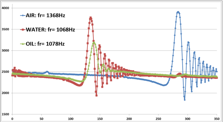
Figure 4-2 shows the ADC data sampled by the MCU. The X-axis represents the 350 periods per sweep, and the Y-axis is the digitized value (0 to 4095). The 80-degree shift of peak amplitude phase delay further increases the selectivity as the input signal decreases before ramping up to the resonance frequency. The three measurements use the same SAC settings (SAC1 with 500-mVDC output, SAC2 gain of 2 V/V, and SAC3 gain of 1 V/V) to demonstrate the amplitude attenuation in the different mediums.
 Figure 4-2 ADC Sample Data of RX Piezo Signal
Note that measurements are taken from a specific tuning fork level sensor. Results and optimum sampling times vary with different types of tuning forks.