SLAAEF5 March 2024 MSPM0G1505 , MSPM0G1505 , MSPM0G1506 , MSPM0G1506 , MSPM0G1507 , MSPM0G1507 , MSPM0L1303 , MSPM0L1303 , MSPM0L1304 , MSPM0L1304 , MSPM0L1304-Q1 , MSPM0L1304-Q1 , MSPM0L1305 , MSPM0L1305 , MSPM0L1305-Q1 , MSPM0L1305-Q1 , MSPM0L1306 , MSPM0L1306 , MSPM0L1306-Q1 , MSPM0L1306-Q1
- 1
- Abstract
- Trademarks
- 1Introduction
- 2Algorithm Introduction
- 3Gauge GUI Introduction
- 4MSPM0 Gauge Evaluation Steps
- 5MSPM0 Gauge Solutions
- 6References
4.4.2 Communication Data Input Mode
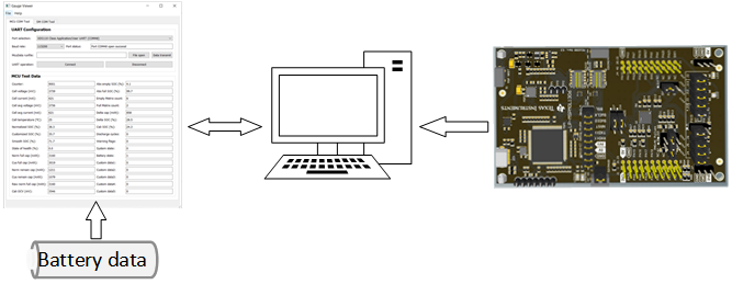
For this mode, the battery running data is input from the GUI. It enables you to run the real test case or evaluate the MSPM0 Gauge with only a LaunchPad. This method can remove the need of hardware, increase algorithm running frequency and have no limit to the length of battery running data.
 Figure 4-12 Communication Data Input Mode
Structure
Figure 4-12 Communication Data Input Mode
Structure- First, to realize this method, you only need a LaunchPad and do the right hardware setting.
- Second, download the gauge code to the launchpad after changing the detection mode to "COMMUNICATION_DATA_INPUT" in "Gauge_UserConfig.h".
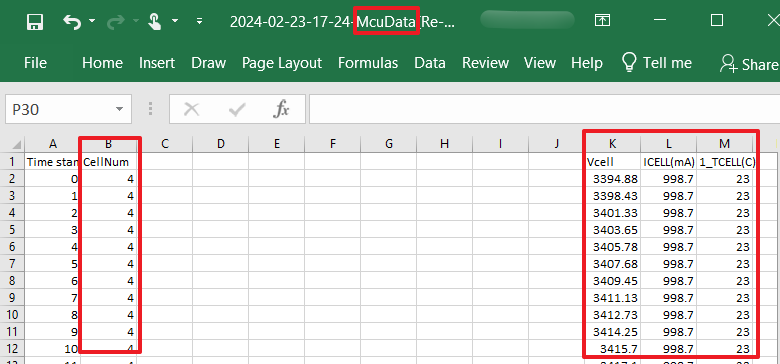
- Third, you need to have a MCUData
file. An introduction is provided on how to transmit a test data into a
recognized file by the GUI, especially for those who do not generate the test
file from GUI. You need to input the Cell num at column B. And then input every
battery's Vcell(mV), Icell(mA) and Tcell(°C) into the same column like the same
McuData file. For this, you can generate a McuData file first and refer to that
one to do the transmit ion. At last, name the file with "-McuData.xlsx".
 Figure 4-13 McuData Type
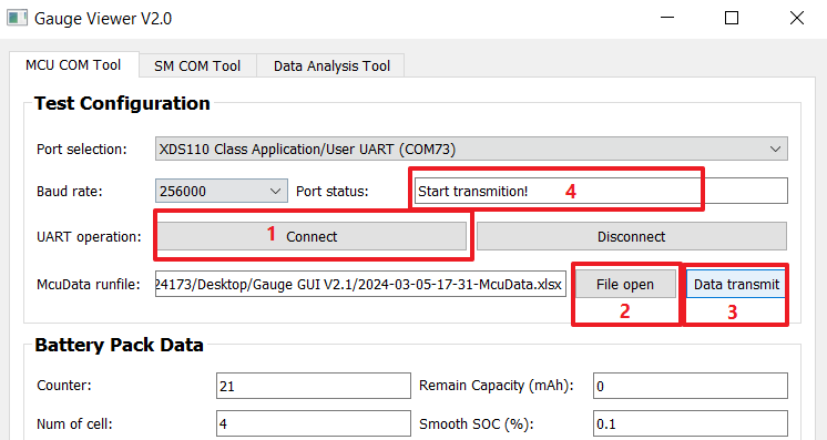
 - Forth, connect the UART COM port
following Figure 4-14 and load the MCUData runfile in MCU COM Tool by clicking the File open
button. After clicking the Data transmit button, you need to wait until the port
status changes to “Start transmit ion!”. The data load time and excel save time
will be long if the file is very large. It would be 5~10 minutes.
 Figure 4-14 Communication Data
Input Steps
You will receive the battery running data from MCU shown in MCU Test Data block. After it finishes transmission, the GUI automatically saves the received data under the GUI address.