SLAAEJ0 November 2023 AM625 , MSPM0C1105 , MSPM0C1106 , MSPM0H3216 , MSPM0L1306
1.1 SPI Transaction Dataflow
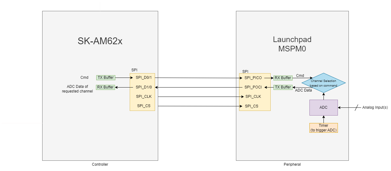
We configure the ADC present on MSPM0L130x Microcontroller and establish an SPI interface with AM62x microprocessor Starter-Kit. Here, AM62x has been configured as the controller and MSPM0L130x as the peripheral. To obtain ADC data from any channel, the controller can initiate a SPI transaction with corresponding command in TX buffer. The peripheral on receiving command from controller starts transmitting the ADC data loaded into its TX buffer based on the channel requested. Controller receives the expected number of bytes from peripheral and then ends the transaction. The peripheral continuously keeps on reading and updating ADC data values. The frequency of these updates depends on the timer used to trigger the ADC. (1)

Pipelining in case Full Duplex SPI when Multi-Channel Mode is used:
In full duplex SPI mode, data is simultaneously transmitted and received over the same set of clock cycles. Hence, in the case of multi-channel ADC usage, when command is sent by controller, it simultaneously receives ADC data corresponding to its last command.
The steps involved in running this application are:
Hardware setup involving connections between SK-AM62x and LP-MSPM0L130x.
Software setup that includes one-time pre-execution steps.
Execution of applications on both boards to enable SPI transactions.
Result analysis.
System performance analysis and power consumption estimation.
Note: The use of “Master” and “Slave”, along with “MOSI/MISO” terminology is being considered obsolete. These terms will be replaced with “Controller” and “Peripheral”, and “PICO/POCI” respectively.