SLASEW8A October 2020 – September 2023 DAC43701-Q1 , DAC53701-Q1
PRODUCTION DATA
- 1
- 1 Features
- 2 Applications
- 3 Description
- 4 Revision History
- 5 Pin Configuration and Functions
-
6 Specifications
- 6.1 Absolute Maximum Ratings
- 6.2 ESD Ratings
- 6.3 Recommended Operating Conditions
- 6.4 Thermal Information
- 6.5 Electrical Characteristics
- 6.6 Timing Requirements: I2C Standard Mode
- 6.7 Timing Requirements: I2C Fast Mode
- 6.8 Timing Requirements: I2C Fast-Mode Plus
- 6.9 Timing Requirements: GPI
- 6.10 Timing Diagram
- 6.11 Typical Characteristics: VDD = 5.5 V (Reference = VDD) or VDD = 5 V (Internal Reference)
- 6.12 Typical Characteristics: VDD = 1.8 V (Reference = VDD) or VDD = 2 V (Internal Reference)
- 6.13 Typical Characteristics
-
7 Detailed Description
- 7.1 Overview
- 7.2 Functional Block Diagram
- 7.3 Feature Description
- 7.4 Device Functional Modes
- 7.5 Programming
- 7.6
Register Map
- 7.6.1 STATUS Register (address = D0h) [reset = 000Ch or 0014h]
- 7.6.2 GENERAL_CONFIG Register (address = D1h) [reset = 01F0h]
- 7.6.3 CONFIG2 Register (address = D2h) [reset = device-specific]
- 7.6.4 TRIGGER Register (address = D3h) [reset = 0008h]
- 7.6.5 DAC_DATA Register (address = 21h) [reset = 0000h]
- 7.6.6 DAC_MARGIN_HIGH Register (address = 25h) [reset = device-specific]
- 7.6.7 DAC_MARGIN_LOW Register (address = 26h) [reset =device-specific]
- 7.6.8 PMBUS_OPERATION Register (address = 01h) [reset = 0000h]
- 7.6.9 PMBUS_STATUS_BYTE Register (address = 78h) [reset = 0000h]
- 7.6.10 PMBUS_VERSION Register (address = 98h) [reset = 2200h]
- 8 Application and Implementation
- 9 Device and Documentation Support
- 10Mechanical, Packaging, and Orderable Information
3 Description
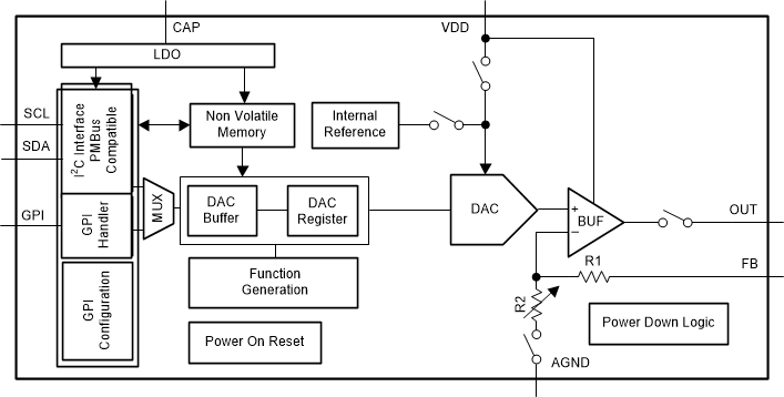
The automotive-grade 10-bit DAC53701-Q1 and 8-bit DAC43701-Q1 (DACx3701-Q1) are a pin-compatible family of buffered voltage-output smart digital-to-analog converters (DACs). These devices consume very low power, and are available in a tiny 8-pin WSON package. The feature set combined with the tiny package and low power make the DACx3701-Q1 an excellent choice for applications such as automotive tail plus brake light, license plate light fade-in fade-out, and PWM expansion for interior light.
These devices have nonvolatile memory (NVM), an internal reference, a PMBus-compatible I2C interface, and a general-purpose input. The DACx3701-Q1 operates with either an internal reference or with the power supply as a reference, and provides a full-scale output of 1.8 V to 5.5 V.
The DACx3701-Q1 are smart DAC devices because of the advanced integrated features. With a force-sense output, GPI based function trigger, PWM output, and NVM capabilities, smart DACs enable system performance and control without the use of software.
| PART NUMBER | RESOLUTION | PACKAGE(1)(2) |
|---|---|---|
| DAC53701-Q1 | 10-bit | DSG (WSON, 8) 2 mm × 2 mm |
| DAC43701-Q1 | 8-bit |
 Functional Block Diagram