SLAU573C November 2015 – October 2019
4.2 BSL Connector and Available Pins
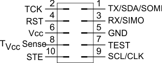
Figure 7 shows the BSL Connector as seen from the target side.
- UART communication is handled through pin 1 (TX) and pin 3 (RX).
- I2C communication is handled through pin 1 (SDA) and pin 9 (SCL).
- SPI communication is handled through pin 1 (SOMI), pin 3 (SIMO), pin 9 (CLK), and pin 10 (STE).
- The entry sequence can be generated using pin 4 (RST) and pin 7 (TEST) for devices with shared JTAG pins, or using pin 2 (TCK) and pin 4 (RST) for devices with dedicated JTAG pins.
- Power is supplied through pin 6 (VCC), and electrical ground is supplied through pin 5 (GND).
The connector uses 0.1-inch spacing and is a 10-pin male header on the target board.
 Figure 7. Pinout of the BSL Connector (Target Side)