SLAU739 October   2017


  1.   MSP430FR2433 LaunchPad™ Development Kit (MSP‑EXP430FR2433)
    1.     Trademarks
    2. 1 Getting Started
      1. 1.1 Introduction
      2. 1.2 Key Features
      3. 1.3 What's Included
        1. 1.3.1 Kit Contents
        2. 1.3.2 Software Examples
      4. 1.4 First Steps: Out-of-Box Experience
        1. 1.4.1 Connecting to the Computer
        2. 1.4.2 Running the Out-of-Box Demo
      5. 1.5 Next Steps: Looking Into the Provided Code
    3. 2 Hardware
      1. 2.1 Block Diagram
      2. 2.2 Hardware Features
        1. 2.2.1 MSP430FR2433 MCU
        2. 2.2.2 eZ-FET Onboard Debug Probe With EnergyTrace Technology
        3. 2.2.3 Debug Probe Connection: Isolation Jumper Block
        4. 2.2.4 Application (or Backchannel) UART
        5. 2.2.5 Optional Features
          1. 2.2.5.1 Supercapacitor
      3. 2.3 Power
        1. 2.3.1 eZ-FET USB Power
        2. 2.3.2 BoosterPack and External Power Supply
        3. 2.3.3 Supercap (C6)
          1. 2.3.3.1 Charging the Supercap
          2. 2.3.3.2 Using the Supercap
          3. 2.3.3.3 Disabling the Supercap
      4. 2.4 Measure Current Draw of the MSP430 MCU
      5. 2.5 Clocking
      6. 2.6 Using the eZ-FET Debug Probe With a Different Target
      7. 2.7 BoosterPack Pinout
      8. 2.8 Design Files
        1. 2.8.1 Hardware
        2. 2.8.2 Software
      9. 2.9 Hardware Change log
    4. 3 Software Examples
      1. 3.1 Out-of-Box Software Example
        1. 3.1.1 Source File Structure
        2. 3.1.2 Overview
        3. 3.1.3 FRAM Data Logging Mode
        4. 3.1.4 Live Temperature Mode
      2. 3.2 Blink LED Example
        1. 3.2.1 Source File Structure
    5. 4 Resources
      1. 4.1 Integrated Development Environments
        1. 4.1.1 TI Cloud Development Tools
          1. 4.1.1.1 TI Resource Explorer Cloud
          2. 4.1.1.2 Code Composer Studio Cloud
        2. 4.1.2 Code Composer Studio IDE
        3. 4.1.3 IAR Embedded Workbench for Texas Instruments 430
      2. 4.2 LaunchPad Websites
      3. 4.3 MSPWare and TI Resource Explorer
      4. 4.4 FRAM Utilities
        1. 4.4.1 Compute Through Power Loss (CTPL)
        2. 4.4.2 Nonvolatile Storage (NVS)
      5. 4.5 MSP430FR2433 MCU
        1. 4.5.1 Device Documentation
        2. 4.5.2 MSP430FR2433 Code Examples
        3. 4.5.3 MSP430 Application Notes and TI Designs
      6. 4.6 Community Resources
        1. 4.6.1 TI E2E Community
        2. 4.6.2 Community at Large
    6. 5 FAQ
    7. 6 Schematics

MSP430FR2433 MCU

The MSP430FR2433 is an ultra-low-power MSP430FRx FRAM-based microcontroller (MCU), which offer extended data logging and security capabilities. The MSP430FR2433 offers the small VQFN package (4 mm × 4 mm) in the FRAM microcontroller portfolio, combined with a variety of integrated peripherals and ultra-low power consumption. FRAM is a cutting edge memory technology, combining the best features of flash and RAM into one nonvolatile memory. More information on FRAM can be found at www.ti.com/fram.

Device features include:

  • 1.8-V to 3.6-V operation
  • 16-bit RISC architecture up to 16-MHz system clock and 8-MHz FRAM access
  • 15KB of program FRAM, 512B of information FRAM, and 4KB of RAM
  • 8-channel 10-bit ADC
  • Four 16-Bit timers
    • Two timers with three capture/compare registers each (Timer_A3)
    • Two timers with two capture/compare registers each (Timer_A2)
  • 32-bit hardware multiplier (MPY)
  • 19 GPIOs
  • Two enhanced universal serial communication interfaces (eUSCI_A) support UART, IrDA, and SPI
  • One eUSCI (eUSCI_B) supports SPI and I2C
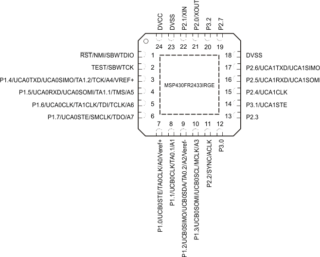
SLAS942_PINOUT_QFN24C.gifFigure 4. MSP430FR2433 Pinout