SLAU835A December 2020 – February 2022 TAS2563
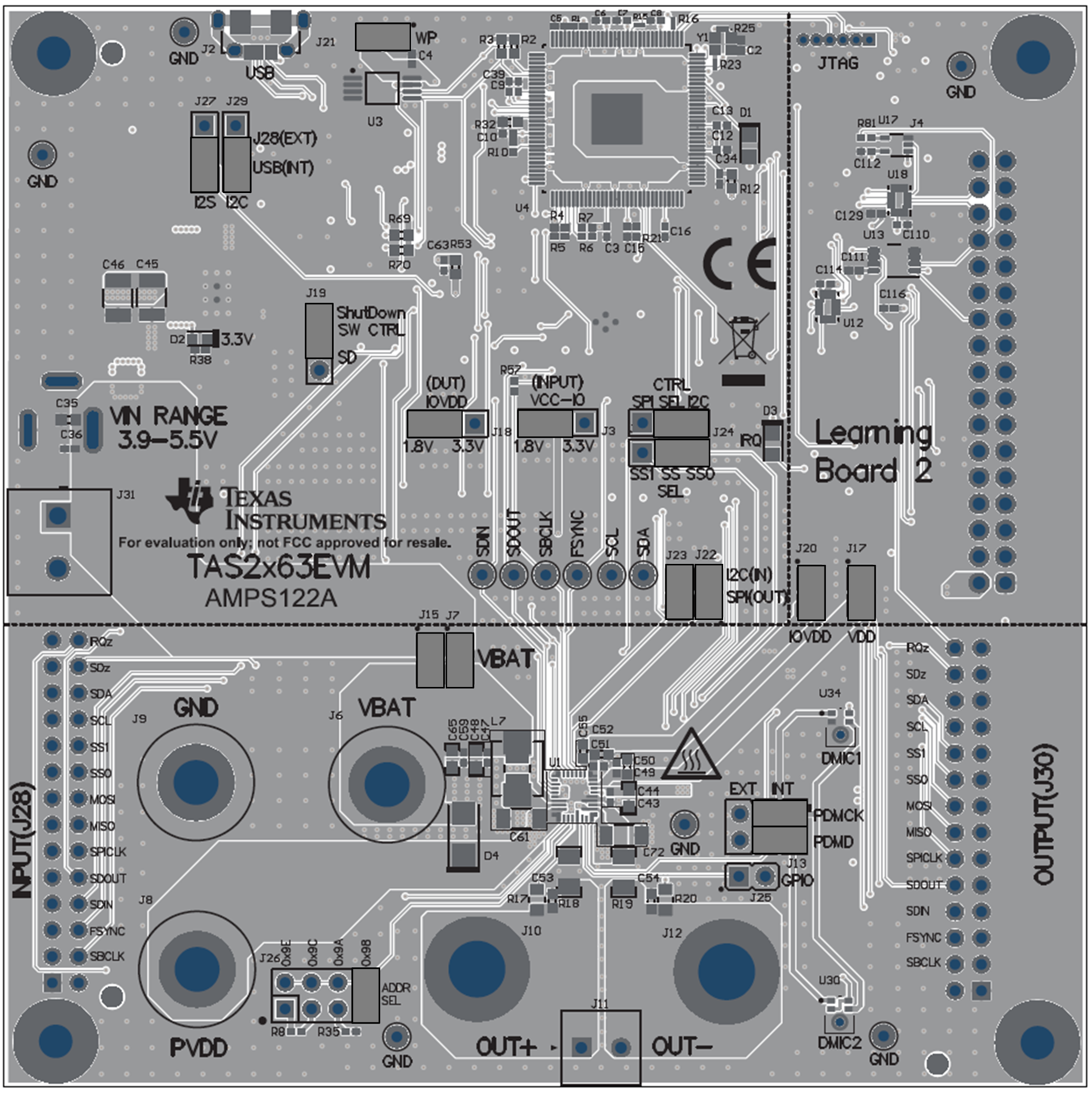
5.1 Default Jumper Settings
Table 5-1 Default Jumper Settings
| Jumper | Setting | Description |
|---|---|---|
| J27 | USB | I2S input from USB |
J29 | USB | I2C input from USB |
J19 | SW CTRL | SD controlled by software |
J18 | 1.8 V | TAS2563 IOVDD voltage |
J3 | 1.8 V | Input signals voltage level |
J24 | I2C | Control signals from I2C |
J22 | Insert | SDA from I2C controls |
J23 | Insert | SCL from I2C controls |
J17 | Insert | VDD current sense |
J20 | Insert | IOVDD current sense |
J7 | Insert | VBAT current sense |
J15 | Insert | VBAT current sense |
J13 | INT | DMICs on the board |
J26 | 0x98 | Address select |
J21 | Insert | EEPROM write protect |
J25 | Remove | GPIO pin |
J5 | Disable | SPI xltr enable control |
 Figure 5-1 Default Jumper Settings