SLLA566A September 2021 – October 2021 SN6501 , SN6501-Q1 , SN6505A , SN6505A-Q1 , SN6505B , SN6505B-Q1 , SN6505D-Q1 , SN6507-Q1
1 Introduction
Electrical isolation is a means of preventing unwanted direct current (DC) and alternating current (AC) between two parts of a system while still enabling signal and power transfer between those two parts. Signal and power isolation is needed in a wide variety of applications for electrical safety, as well as for the protection of sensitive circuitry under fault conditions, to protect human operators and low-voltage circuitry from high voltages, to improve noise immunity, and to safely withstand ground potential differences between communicating circuits.
Isolated power is traditionally generated using a DC/DC converter to drive a transformer in flyback, fly-buck or push-pull topologies, where pulsating signals on the secondary side of an isolation transformer are rectified and filtered to generate an isolated DC supply. Push-pull isolated power topologies, like those that can be created using SN6501 and SN6505 transformer drivers, offer unique advantages as isolated power solutions, like a higher typical power transfer efficiency of 75-90% due to the external transformer, the option to minimize emissions by using lower switching frequencies, and the benefits of using push-pull power supplies go on to include simplicity in design and component selection, even greater power supply efficiencies due to low parasitic peak currents, off-the-shelf transformer options, requirements allowing for smaller transformers, inherent immunity from transients due to tight coupling of transformer windings, and low electromagnetic emissions due to symmetry of the topology.
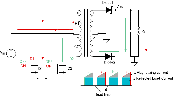
In discrete solutions, TI's transformer driver family, SN650x, enable higher power delivery with up to 1A at 5V. Push-pull drivers use center-tapped transformers to transfer power from primary side to secondary side, as shown in Figure 1-1. The symmetric drivers Q1 and Q2 are clocked such that when one is ON the other one is OFF and vice versa. The driver timing also incorporates a dead time between the ON times where both the FETs are OFF so that the primary never gets shorted. Push pull topologies are inherently robust from an EMC perspective as the drives are differential in nature, unlike single ended topologies. Common mode energy transfers across the barrier are limited as the rise and fall of drivers are almost identical in either case of Q1 or Q2 being ON, implying that D1 and D2 are always complementary in nature. This is mostly because the primary windings of the push-pull transformer are tightly coupled from construction.
 Figure 1-1 Complementary Energy Transmission by Push-pull Power Supplies
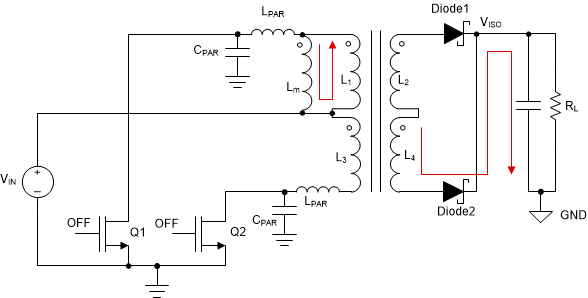
Transformers inherently have multiple parasitics. They have a magnetizing inductance component due to finite permeability of the core material, and there is a component of core resistance in parallel to this magnetizing inductance that can be attributed to eddy losses and core losses. There is also a component of leakage inductances and winding resistances that can be attributed to flux leakage and finite conductivity of the winding. These transformer parasitics along with the trace and drive FET off capacitances (capacitance present when the FET is OFF), create an LC network that rings at a particular frequency which hence induces common mode currents, as shown in Figure 1-2. This is observed as significant ringing during the FET dead time of the switching period, and this common mode current across the barrier is one the source of radiated emissions.
 Figure 1-2 Push-pull Isolated Power Supply with Switching Parasitics Create a Ringing LC Network
In this document, we will examine how to reduce the already-low radiated emissions of push-pull isolated power supplies by analyzing emissions using TI’s SN6505B push-pull isolation transformer driver. Using experimental data, we will demonstrate how the addition of snubber circuits to the SN56505 switching power lines can be used to compensate for push-pull transformer supply parasitics by reducing emissions.