SLLA609 September 2023 ISOM8110 , ISOM8710 , ISOM8711
3 What is an Opto-Emulator?
Texas Instruments opto-emulators combine the behavior of traditional optocouplers with TI’s SiO2-based isolation technology. Figure 3-1 shows that opto-emulators are pin-to-pin compatible with the industry’s most popular optocouplers, facilitating seamless integration into existing designs and providing equivalent input and output signal behavior.
 Figure 3-1 Functional Comparison of
Optocoupler (Left) and Opto-emulator (Right)
Figure 3-1 Functional Comparison of
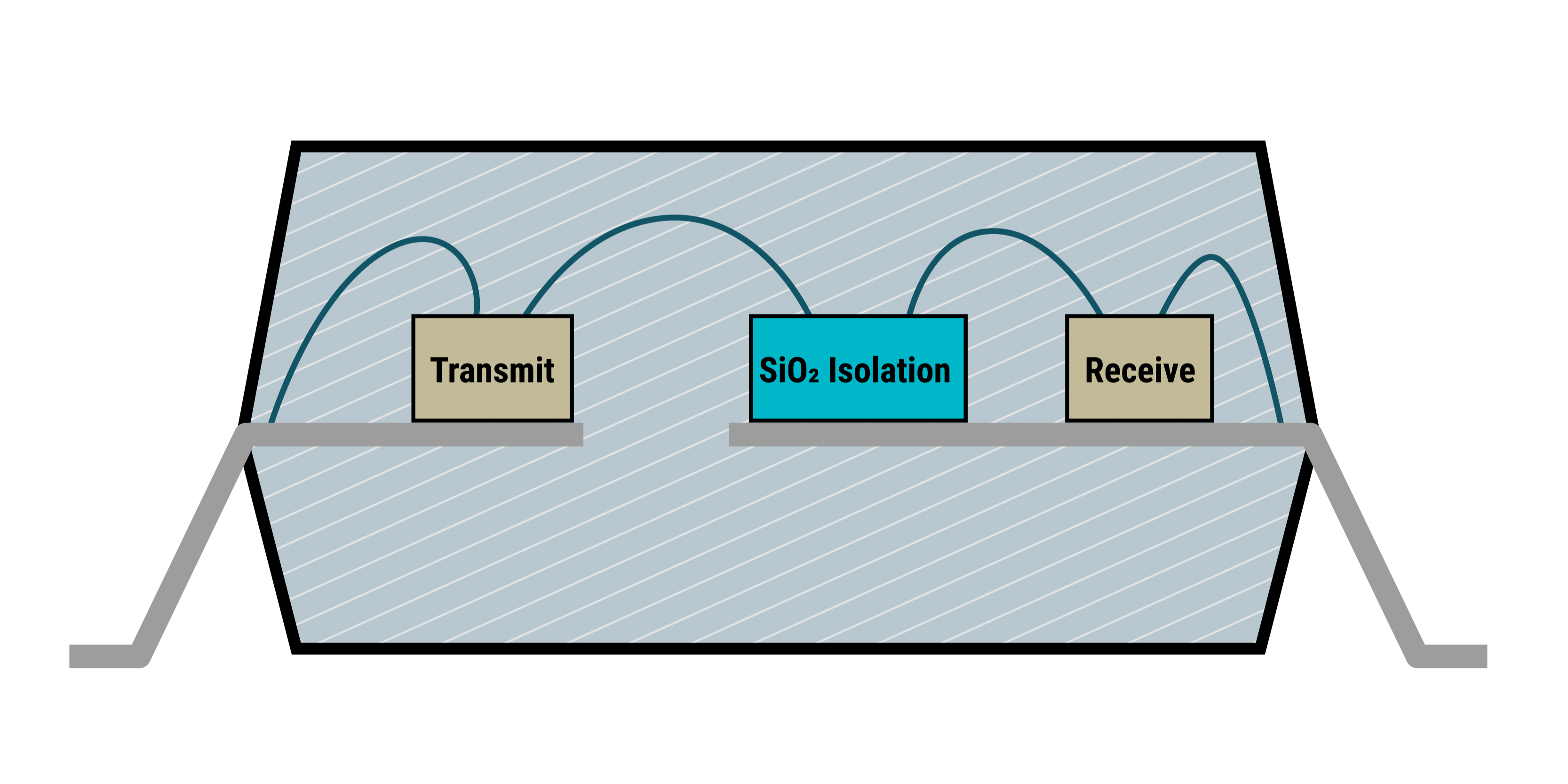
Optocoupler (Left) and Opto-emulator (Right)Figure 3-1 is an illustrative cross section of a TI opto-emulator, showing the three die inside which contain input, isolation, and output circuitry.
 Figure 3-2 Cross Section of Opto-Emulator
| Insulator Materials | Technology | Dielectric Strength |
|---|---|---|
| Air | Optocouplers | approximately 1 VRMS/µm |
| Epoxies | Optocouplers | approximately 20 VRMS/µm |
| Silica Filled Mold Compounds | Optocouplers | approximately 100 VRMS/µm |
| SiO2 | Opto-emulators | approximately 500 VRMS/µm |
TI's opto-emulators replicate the behavior of an LED on the input pins, so the signal transmission and electrical parameters of the input circuit are similar to that of optocouplers. However, there is no actual LED inside of opto-emulators, which results in several benefits:
- Since there is no internal LED for signal transmission or transparent insulation material that can cloud or yellow with time, the additional power that optocouplers require to compensate for this degradation over their entire lifetime is not required when using TI’s opto-emulators. Since opto-emulators do not transmit signals using an LED, this over design practice does not apply. The signal transmission, power consumption, and other operating parameters for TI’s opto-emulators are specified for their entire operating lifetime and already account for process, voltage, and temperature variations.
- Building on TI's existing digital isolator technology, TI's first high-speed opto-emulator devices, the ISOM871x family, feature a minimum CMTI specification of 125 kV/µs, surpassing some traditional optocouplers by >100 kV/µs! This allows opto-emulators to be used in applications with very high common-mode switching noise or high ringing amplitudes where traditional optocouplers cannot be used.
- In typical applications, like in feedback control loops of isolated power supplies, CTR variation of optocouplers impacts the power supply feedback loop response, complicating feedback loop design and creating challenges for system designers when factoring in the appropriate compensation. TI opto-emulators, like the ISOM8110, come standard with a variety of narrow CTR ranges that have higher stability over lifetime and temperature.
- Typical high-speed optocouplers support data rates from 100kbps up to 1Mbps, while ISOM8710 and ISOM8711 can transmit data rates up to 25Mbps across the isolation barrier. This enables higher throughput and use in more high-speed applications.
- Many optocouplers are limited to operation in temperatures up to +85°C. TI’s ISOM871x devices are specified for operation from −40°C to +125°C, meaning their data sheet parameters are specified for conditions many high-speed optocouplers are not designed for. TI's ISOM811x family of opto-emulators support a further extended temperature range of –55°C to +125°C.
TI's opto-emulators achieve signal isolation much like our digital isolator devices. The emulation in opto-emulators refers to the recreation of input and output structures that operate like optocouplers while isolating signals using TI's isolation technology.
Standard optocouplers use an LED as the input stage. When the input is turns the diode ON, these LEDs brighten as input forward current increases. The light from the LED shines through an air or epoxy gap onto a photo transistor inside of the package, which in turn sinks current on the output side. This is the core operation of optocouplers, where the isolation barrier is the air or epoxy gap between the LED and photo transistor, and additional circuitry can be designed around the input or output create AC inputs or logic, triac, or gate-driver outputs.
In opto-emulators, the input signal is transmitted across the isolation barrier using an on-off keying (OOK) modulation scheme. The transmitter sends a high frequency carrier across the barrier to represent one digital state and sends no signal to represent the other digital state. Signal transmission in analog opto-emulators functions similarly, and a receiver demodulates the signal after advanced signal conditioning and produces the signal through the output stage. The concept of the OOK modulation scheme is shown by the waveforms in Figure 3-3.
 Figure 3-3 On-Off Keying Based Modulation
Scheme