SLLSEV9E July   2016  – November 2023 TUSB522P

PRODUCTION DATA  

  1.   1
  2. Features
  3. Applications
  4. Description
  5. Revision History
  6. Pin Configuration and Functions
  7. Specifications
    1. 6.1 Absolute Maximum Ratings
    2. 6.2 ESD Ratings
    3. 6.3 Recommended Operating Conditions
    4. 6.4 Thermal Information
    5. 6.5 Electrical Characteristics, Power Supply
    6. 6.6 Electrical Characteristics, DC
    7. 6.7 Electrical Characteristics, AC
  8. Detailed Description
    1. 7.1 Overview
    2. 7.2 Functional Block Diagram
    3. 7.3 Feature Description
      1. 7.3.1 Receiver Equalization
      2. 7.3.2 De-Emphasis Control and Output Swing
      3. 7.3.3 Automatic LFPS Detection
    4. 7.4 Device Functional Modes
      1. 7.4.1 Device Configuration
      2. 7.4.2 Power Modes
        1. 7.4.2.1 U0 Mode (Active Power Mode)
        2. 7.4.2.2 U2/U3 (Low Power Mode)
        3. 7.4.2.3 Disconnect Mode - RX Detect
        4. 7.4.2.4 Shutdown Mode
  9. Application and Implementation
    1. 8.1 Application Information
    2. 8.2 Typical Application
      1. 8.2.1 Design Requirements
      2. 8.2.2 Detailed Design Procedure
        1. 8.2.2.1 ESD Protection
      3. 8.2.3 Application Curves
    3. 8.3 Power Supply Recommendations
    4. 8.4 Layout
      1. 8.4.1 Layout Guidelines
      2. 8.4.2 Layout Example
  10. Device and Documentation Support
    1. 9.1 Receiving Notification of Documentation Updates
    2. 9.2 Support Resources
    3. 9.3 Trademarks
    4. 9.4 Electrostatic Discharge Caution
    5. 9.5 Glossary
  11. 10Mechanical, Packaging, and Orderable Information

Detailed Design Procedure

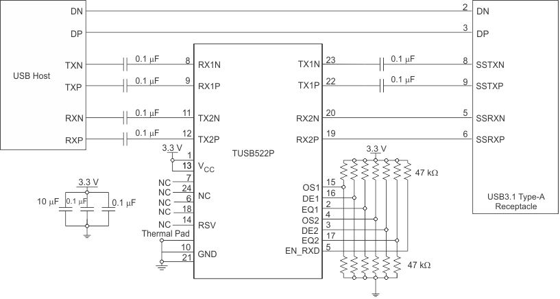
The TUSB522P differential receivers and transmitters have internal BIAS and termination. Due to this, the TUSB522P must be connected to the USB Host and receptacle through ac-coupling capacitors. In this example, as depicted in Figure 8-2, 100 nF capacitors are placed on TX2P, TX2N, RX1P, RX1N, TX1P and TX1N. No ac-coupling capacitors are placed on the RX2P and RX2N pins because it is assumed the device downstream of the TUSB522P will have ac-coupling capacitors on its transmitter as defined by the USB 3.1 specification. The system designer may desire to support short to VBUS protection. If this is the case, then a 330 nF ac-coupling capacitor should be placed on RX2P/N pins.
GUID-7A8DE163-95EC-4199-94DC-85A01DE878D7-low.gif Figure 8-2 Embedded Host Application Schematic