SLLSFC6E November 2021 – July 2025 ISOUSB111
PRODUCTION DATA
- 1
- 1 Features
- 2 Applications
- 3 Description
- 4 Pin Configuration and Functions
-
5 Specifications
- 5.1 Absolute Maximum Ratings
- 5.2 ESD Ratings
- 5.3 Recommended Operating Conditions
- 5.4 Thermal Information
- 5.5 Power Ratings
- 5.6 Insulation Specifications
- 5.7 Safety-Related Certifications
- 5.8 Safety Limiting Values
- 5.9 Electrical Characteristics
- 5.10 Switching Characteristics
- 5.11 Insulation Characteristics Curves
- 5.12 Typical Characteristics
- 6 Parameter Measurement Information
-
7 Detailed Description
- 7.1 Overview
- 7.2 Functional Block Diagram
- 7.3
Feature Description
- 7.3.1 Power Supply Options
- 7.3.2 Power Up
- 7.3.3 Symmetric Operation, Dual-Role Port, and Role-Reversal
- 7.3.4 Connect and Speed Detection
- 7.3.5 Disconnect Detection
- 7.3.6 Reset
- 7.3.7 LS/FS Message Traffic
- 7.3.8 L2 Power Management State (Suspend) and Resume
- 7.3.9 L1 Power Management State (Sleep) and Resume
- 7.4 Device Functional Modes
- 8 Application and Implementation
- 9 Device and Documentation Support
- 10Revision History
- 11Mechanical, Packaging, and Orderable Information
8.3.1.1 Layout Example
The layout example in this section shows
the recommended placement for de-coupling capacitors and ESD protection diodes. A
continuous ground plane is recommended below the D+/D- signal traces. Small
footprint capacitors (0402/0201) are recommended so that these can be placed very
close to the supply pins and corresponding ground pins and connected using the top
layer. There must not be any vias in the routing path between the decoupling
capacitors and the corresponding supply and ground pins. The ESD
protection diodes must be placed close to the connector with a strong connection to
the ground plane. The example shown is for an isolated host or hub, but
similar considerations apply for isolated peripherals also. The 120-μF capacitor on
VBUS only applies to host or hub and must not be used for peripherals. A ferrite
bead, with DC resistance less than 100 mΩ, can be optionally placed on the VBUS
route, after the 100-nF (and 120-μF) capacitors to prevent transients such as ESD
from affecting the rest of the circuits.
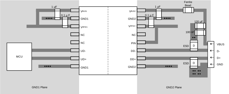 Figure 8-6 Layout Example for
ISOUSB111
For best performance, minimizing the length of D+/D- board traces from the MCU to ISOUSB111, and from ISOUSB111 to the connector is recommended. Vias and stubs on D+/D- lines must be avoided.
Figure 8-6 Layout Example for
ISOUSB111