SLLU342 May 2022 TCAN1462-Q1
- Trademarks
- 1Introduction
-
2EVM Setup and Operation
- 2.1
Overview and Basic Operation Settings
- 2.1.1 VCC Power Supply (J2, J3, J9, and TP10)
- 2.1.2 I/O Power Supply VIO (J2, J10, and TP8)
- 2.1.3 Main Supply and I/O Header (J2)
- 2.1.4 TXD Input (J2 or TP6)
- 2.1.5 RXD Output (J2 or TP7)
- 2.1.6 STB or Pin 8 (J1, J2, or TP1)
- 2.1.7 J1 Configuration
- 2.1.8 TP1 Configuration
- 2.1.9 VIO or Pin 5 (J2, J10, or TP8)
- 2.1.10 J10 Configurations
- 2.1.11 J2 Configuration
- 2.1.12 SIC Network Configuration (J7 & J8)
- 2.2 Using CAN Bus Load, Termination, and Protection Configurations
- 2.3 Using Customer Installable I/O Options for Current Limiting, Pullup and Pulldown, Noise Filtering
- 2.1
Overview and Basic Operation Settings
- 3CAN EVM Configuration for TCAN1462-Q1 (Factory Installed)
1.2 CAN EVM
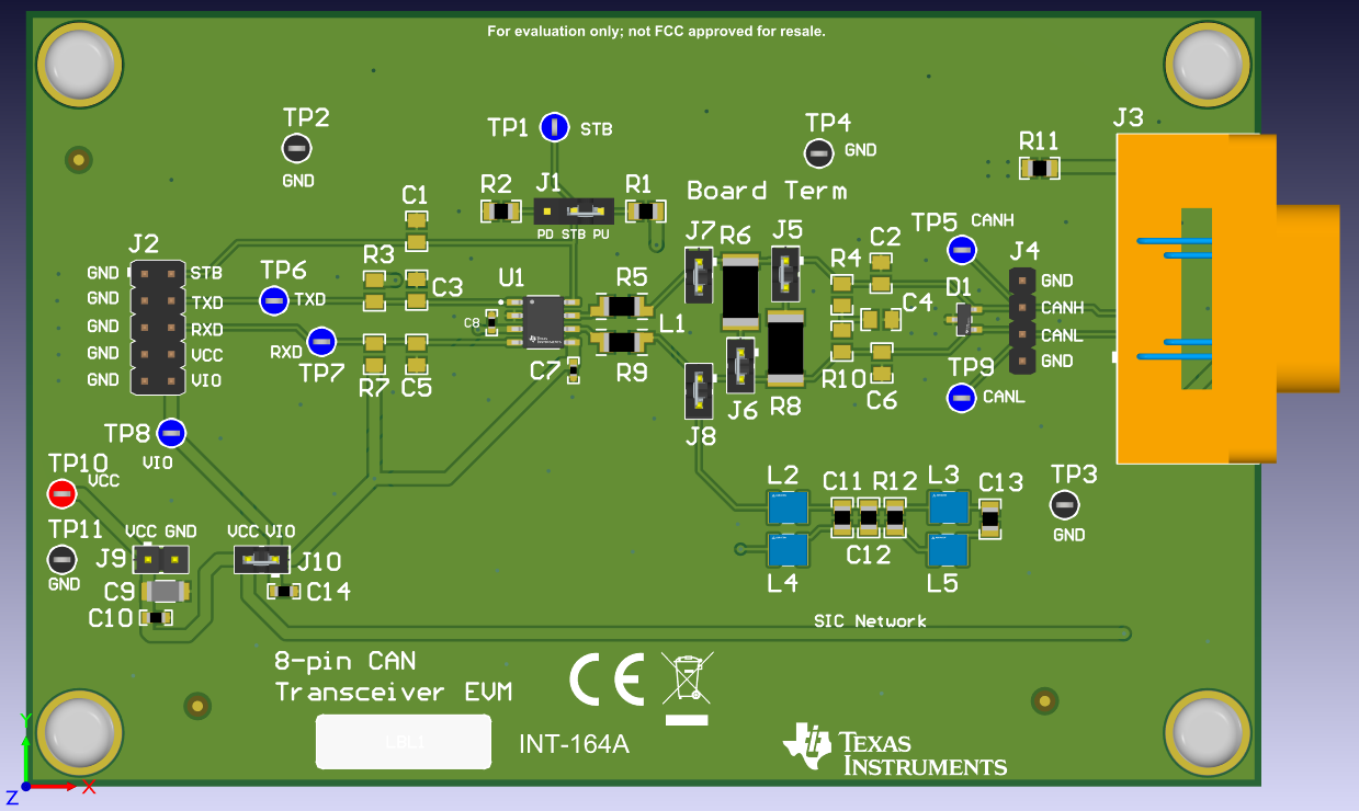
The CAN EVM has simple connections to all necessary pins of the CAN transceiver device, and jumpers where necessary to provide flexibility for device pin and CAN bus configuration. There are test points (loops) for all main points where probing is necessary for evaluation such as GND, VCC, TXD, RXD, CANH, CANL, pin 8 (mode pin), or pin 5 (VIO or NC). The EVM supports many options for CAN bus configuration. It is pre-configured with two 120-Ω resistors that are connected on the bus via jumpers: a single resistor is used with the EVM as a terminated line end (CAN is defined for 120-Ω impedance twisted pair cable) or both resistors in parallel for electrical measurements representing the 60-Ω load the transceiver detects in a properly terminated network (that is, 120-Ω termination resistors at both ends of the cable). If the application requires “split” termination, TVS diodes for protection, or Common Mode (CM) Choke, the EVM has footprints available for this via customer installation of the desired components.
This EVM also has the ability to connect a SiC network, as defined in CIA601-4, to the CAN bus lines via J7 and J8. Connecting the SIC network to CANH and CANL simulates a noisy CAN bus by adding more reflections and ringing to the signals. This can be used to test the reliability of the transceiver in a very noisy environment.
Figure 1-1 shows the EVM board image.
 Figure 1-1 EVM PC
Board