SLOA188A October 2013 – November 2021 DRV2603 , DRV2604 , DRV2605 , DRV2605L-Q1 , DRV2624 , DRV2625
1 Introduction
The DRV260x and DRV262x families of devices use a unique LRA control algorithm called auto-resonance tracking. Auto-resonance tracking uses the back-EMF of an LRA to detect and track the resonance frequency. The DRV260x and DRV262x devices then uses this resonance frequency information to drive the LRA in closed loop. Auto-resonance provides numerous benefits and eases the integration of LRAs:
- Stronger and more consistent vibrations across actuators
- Lower power consumption while driving at resonance
- The ability to overdrive and brake an LRA and achieve better response time
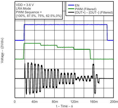
Figure 1-1 shows the input and output signals in an auto-resonance tracking system.
 Figure 1-1 LRA Auto-Resonance Detection
The green waveform is the (PWM) input to the DRV2605 and is a filtered PWM-modulated DC signal representing the waveform envelope or amplitude of the output waveform. The black line represents the sine wave output generated by the DRV2605 with the detected resonant frequency. The DRV2625 does not have a PWM input but the same functionality is achieved using the Real Time Playback (RTP) registers of the device, where instead of setting a physical voltage level on a pin you would set a voltage level via an 8-bit value using I2C.