SLOA247C July 2017 – March 2019 RF430FRL152H , RF430FRL153H , RF430FRL154H
-
Frequently asked questions for RF430FRL15xH devices
- Trademarks
- 1
General Questions
- 1.1 What is the RF430FRL15xH?
- 1.2 What are the variations of the RF430FRL15xH?
- 1.3 What is the recommended hardware and software to evaluate the RF430FRL15xH?
- 1.4 I cannot purchase a TRF7970AEVM. How do I use the RF430FRL152HEVM GUI?
- 1.5 Does the RF430FRL15xH support NDEF messages?
- 1.6 What RF communication range can be expected with the RF430FRL15xH?
- 2
Hardware and Design Questions
- 2.1 What TI Designs are available for the RF430FRL152H?
- 2.2 How do I design and tune an antenna to 13.56 MHz for my application?
- 2.3 Why are the various external components required?
- 2.4 How much power can be sourced from the RF430FRL15xH?
- 2.5 What battery can be used with the RF430FRL15xH?
- 2.6 How should the switches be set on the RF430FRL152HEVM?
- 2.7 How can an external sensor be connected on the RF430FRL152HEVM?
- 2.8 What kinds of analog sensors can be used?
- 2.9 How can a digital sensor be used?
- 2.10 How can the internal temperature sensor be used?
- 2.11 What are the settings to program the RF430FRL152HEVM with an MSP-FET tool?
- 2.12 Is there a low-voltage programmer suitable for the RF430FRL15xH?
- 3
Software Questions
- 3.1 How is the RF430FRL15xH ROM library used?
- 3.2 What example firmware is available for the RF430FRL15xH?
- 3.3 Is there an Android app available to interface with the RF430FRL15xH?
- 3.4 What is the procedure to change between 4- and 8-byte ISO/IEC 15693 blocks?
- 3.5 How can custom ISO/IEC 15693 commands be sent and received?
- 3.6 How can a simple SD14 ADC conversion be set up and executed, and the result read back?
- 3.7 Where is the software for the TIDM-RF430-TEMPSENSE EVM?
- 4 Miscellaneous Questions
- 5 References
- Revision History
2.3 Why are the various external components required?
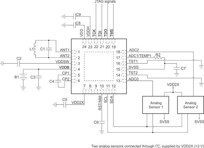
Figure 1 and Table 2 show the external components that are needed for the RF430FRL152H to operate.
 Figure 1. RF430FRL15xH Application Circuit
 Table 2. External Capacitors
| Name | Value | Description | Comment |
|---|---|---|---|
| C4 | 10 nF | Charge pump capacitor | Needed for proper device operation |
| C5 | 100 nF | Decoupling cap at VDD2X | Needed for proper device operation |
| C7 | 1 µF | Bypass capacitor between SVSS and VSS | For proper ADC operation |
| C6 | 10 nF | Decoupling cap at RST | To prevent noise and unintentional resets |
| C2 | 2.2 µF | Decoupling cap at VDDSW | Power supply decoupling |
| C8 | 100 nF | Decoupling cap at VDD | Digital logic decoupling |
| C9 | 100 nF | Decoupling cap at VDDH | Power supply decoupling |
| C3 | 100 nF | Decoupling cap at VDDB (if a battery is being used) | To reduce ESR on a battery |
When using the ROM library, as with the "Default" and "SensorHub" examples, some external resistors may be necessary. See Table 3 for specifics. If using the "NFC" example, this section does not apply.
Table 3. External Resistors
| Pin | Value | Description | Comment |
|---|---|---|---|
| 19 (P1.7) | 10 kΩ to 100 kΩ |
Pullup: External host controller Pulldown: Digital sensor used |
If neither host controller nor digital sensor is used, then use a pullup. Also this pin can be reused for JTAG. |
| 20 (P1.6) | 10 kΩ to 100 kΩ |
I2C address set bit 1 of I2C address SPI mode: sets the SPI Mode (1-4) |
Necessary only if host controller mode is being used. Is a don't care when digital sensor mode is used. Also this pin can be reused for JTAG. |
| 21 (P1.5) | 10 kΩ to 100 kΩ |
I2C mode: set bit 0 of I2C address SPI mode: sets the SPI Mode (1-4) |
Necessary only if host controller mode is being used. Is a don't care when digital sensor mode is used. Also this pin can be reused for JTAG. |
| 8 (P1.3) | Tie to GND or float |
Tie low to enable I2C slave functionality for host controller. High or floating on start-up enables SPI functionality for host controller. |
Necessary only if host controller mode is being used. Is a don't care when digital sensor mode is used. |
For more information, see the section on interfacing a host controller in the RF430FRL15xH firmware user's guide.